
Connector Molding
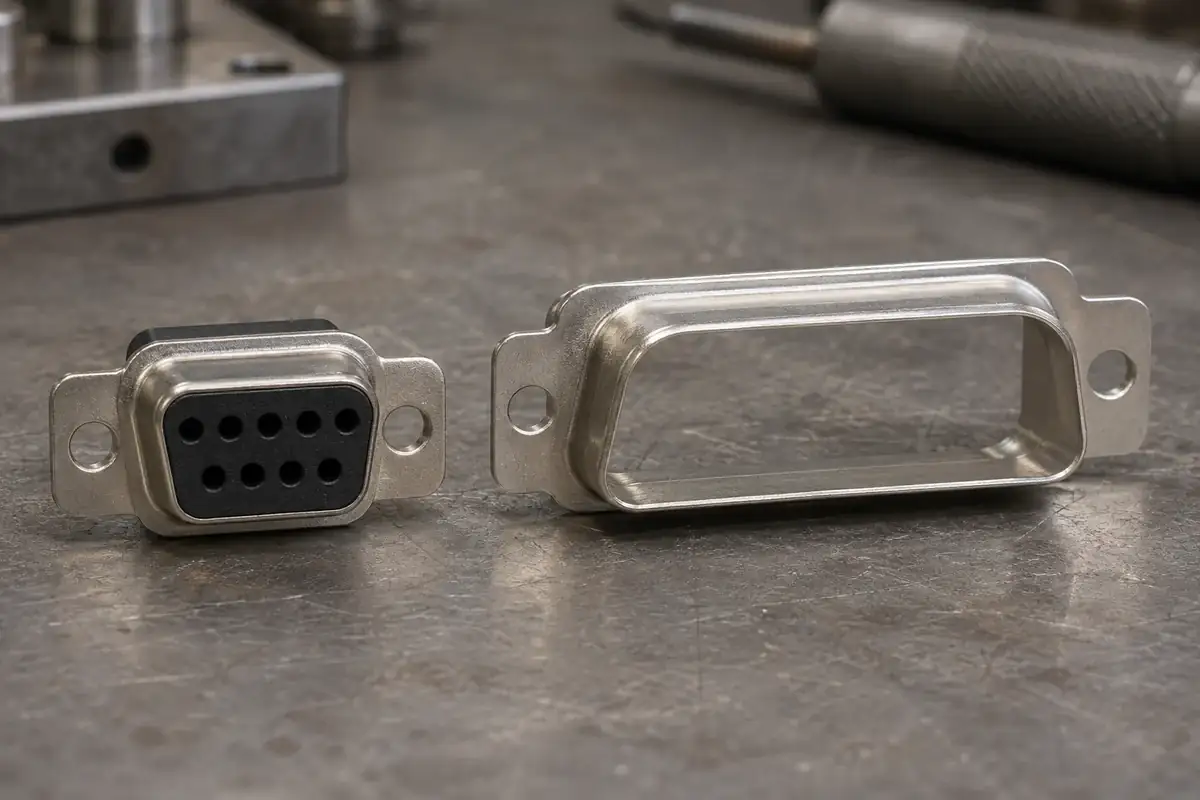
DB9 vs DE9: Naming a D-Sub Correctly on a Drawing
Resolve DB9 and DE9 naming before quoting a molded D-sub insulator. Define shell size, contact arrangement, gender, termination and the controlled drawing view.
Read articleBlog topic
Explore connector housing and insulator molding, material behavior, assembly interfaces and production decisions.
Latest first 109 articles
Connector Molding
Resolve DB9 and DE9 naming before quoting a molded D-sub insulator. Define shell size, contact arrangement, gender, termination and the controlled drawing view.
Read article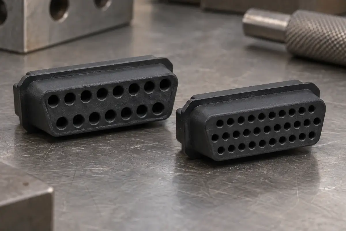
Connector Molding
Compare standard and high-density D-sub inserts through hole layout, plastic webs, contact support, molding access and rear termination space before tooling.
Read article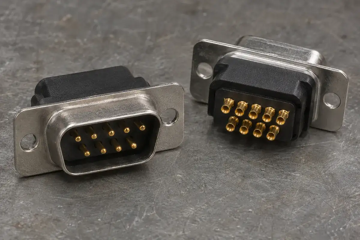
Connector Molding
Avoid mirrored D-sub hole and wiring layouts by defining the viewing face, orientation references, cavity identities and the relationship to assembly tooling.
Read article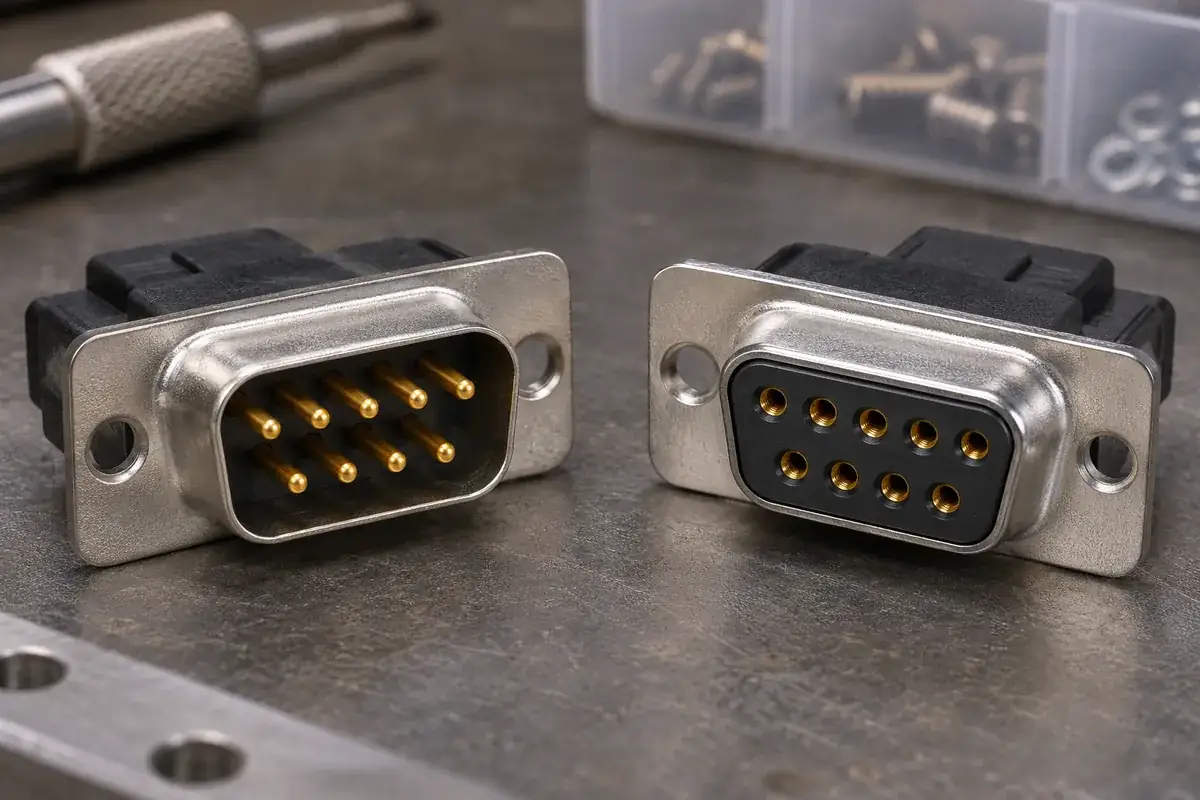
Connector Molding
Understand D-sub pin and socket cavity differences through contact shoulders, entry guidance, retention and assembly access before copying an insulator design.
Read article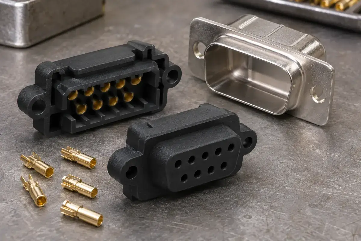
Connector Molding
Review two-piece D-sub insulators through locating features, contact capture, joint condition, shell support and inspection references before releasing tooling.
Read article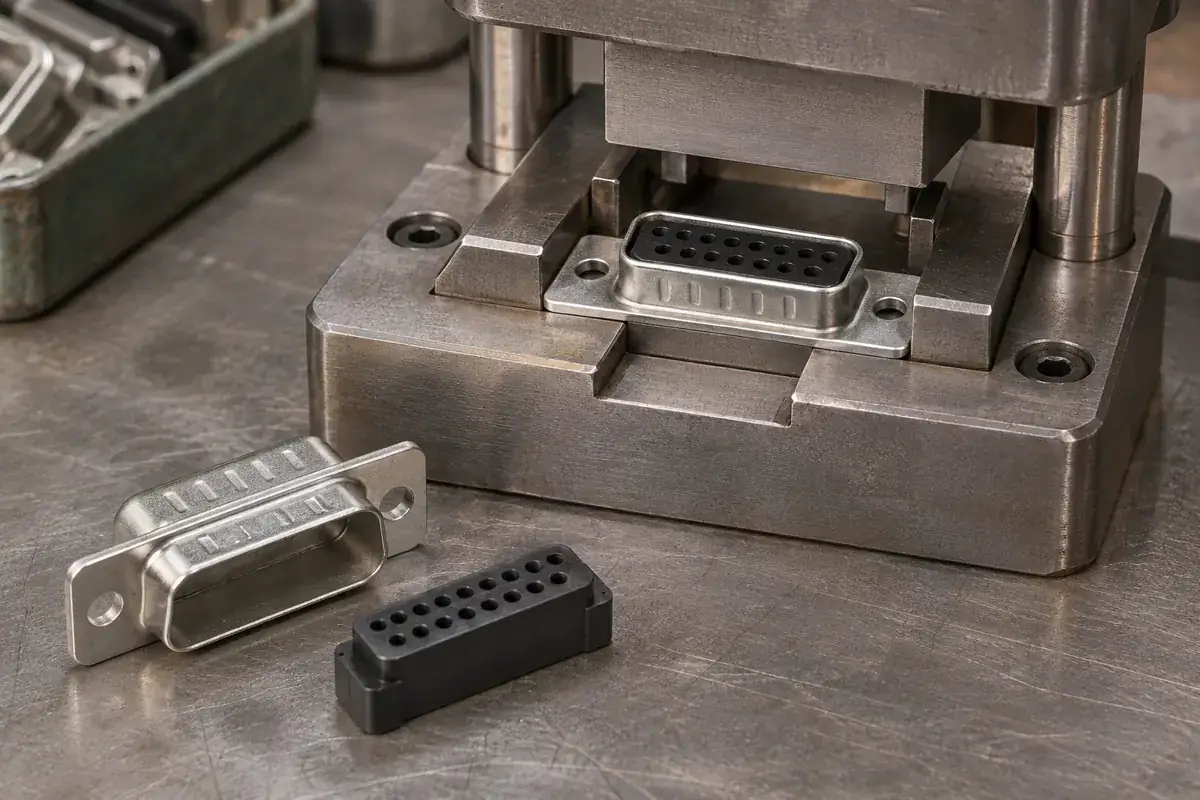
Connector Molding
Review D-sub shell closure through seating, forming support, retaining features and inspection so metal assembly does not damage the molded plastic insert.
Read article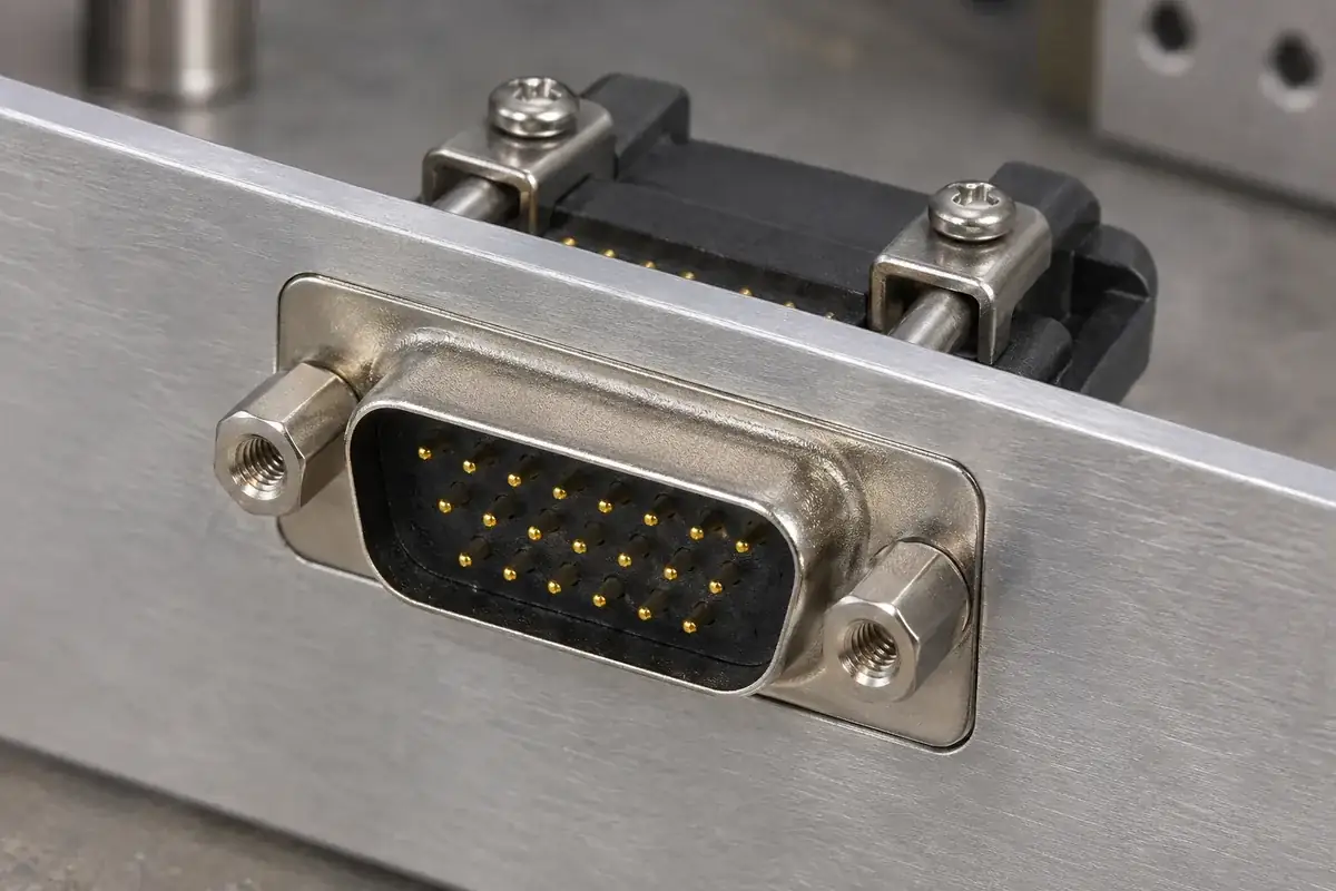
Connector Molding
Review D-sub mounting ears, jackscrews and panel interfaces together to prevent hardware misalignment from loading the molded insulator during installation.
Read article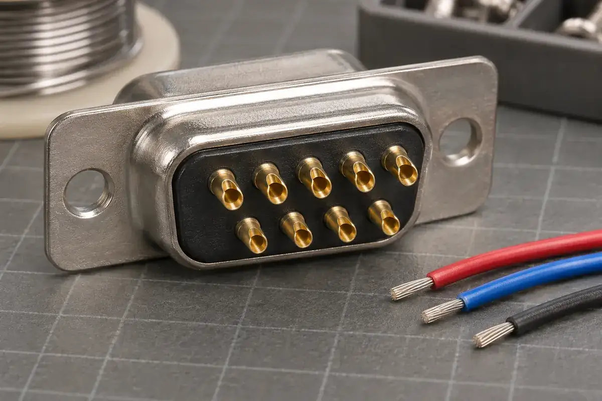
Connector Molding
Plan D-sub solder-cup access around wire insulation, termination sequence, tool approach and backshell space while preserving the molded insulator interfaces.
Read article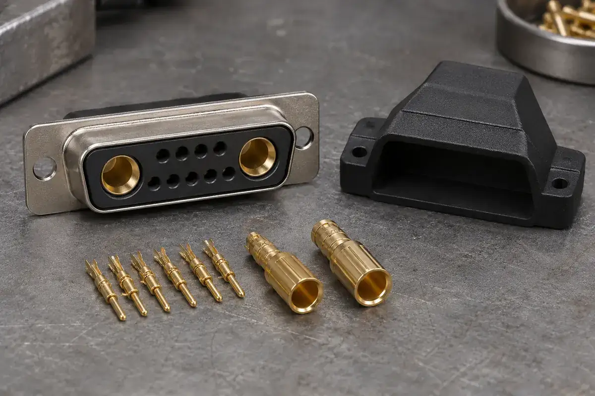
Connector Molding
Review mixed-contact D-sub inserts through large and small cavity envelopes, retention features, insulating paths, tooling access and rear wire routing.
Read article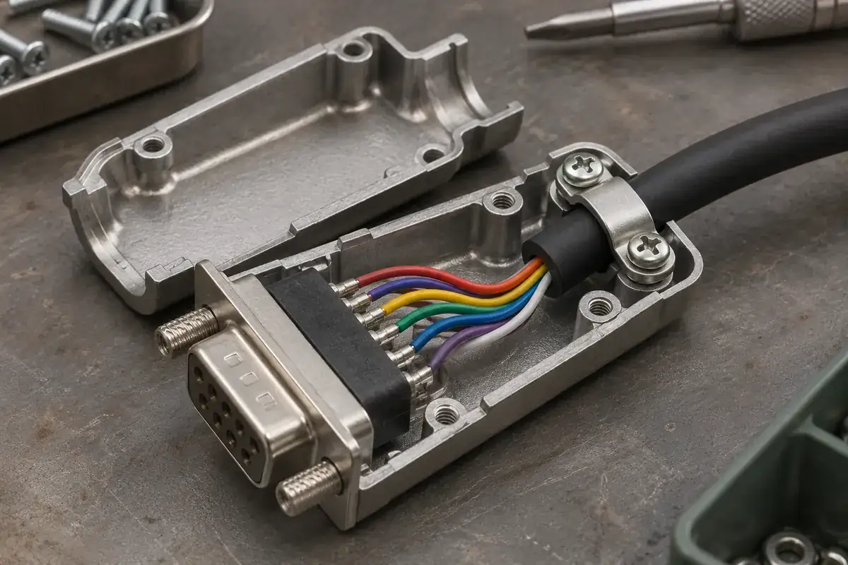
Connector Molding
Trace cable loads through a D-sub backshell, jacket clamp and mounting interface so wire routing and strain relief protect the molded contact insulator.
Read article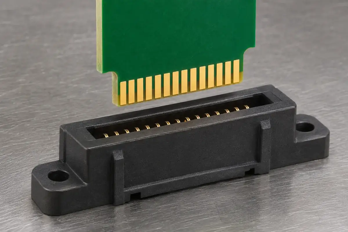
Connector Molding
Review card edge board thickness through the finished PCB, molded slot, spring contacts and installed supports before accepting a connector fit sample.
Read article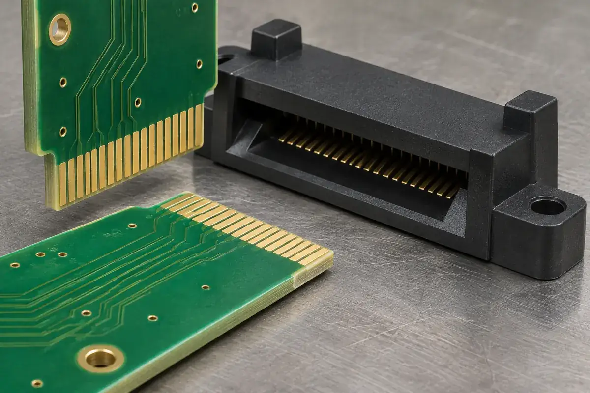
Connector Molding
Understand how the PCB edge bevel and molded socket entrance affect different stages of card insertion, and review their geometry without masking misalignment.
Read article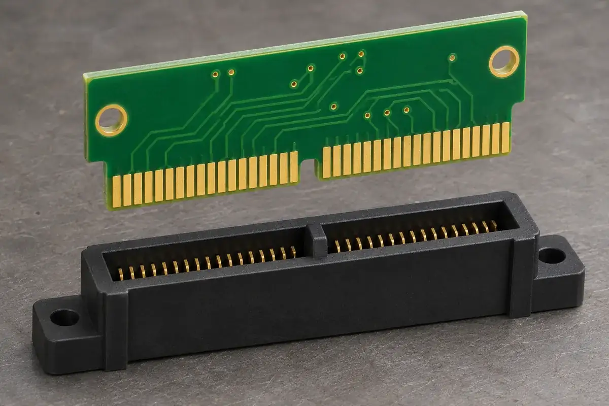
Connector Molding
Locate a card edge polarizing notch by reviewing the contact pattern, board outline, connector key and insertion sequence before releasing molded housing geometry.
Read article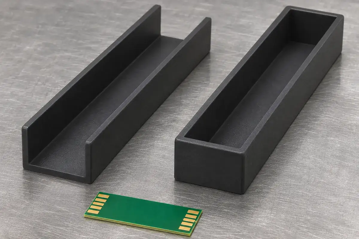
Connector Molding
Compare open and closed card edge housing ends through board width, lateral location, support and molding requirements before selecting a custom slot structure.
Read article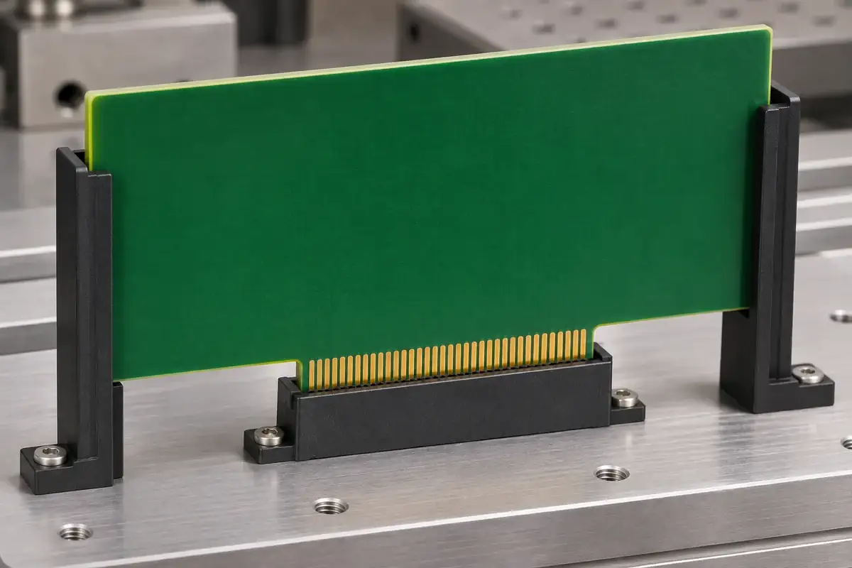
Connector Molding
Review how card guides, brackets and connector housings share the loads of a long PCB during insertion, installed use and removal without conflicting references.
Read article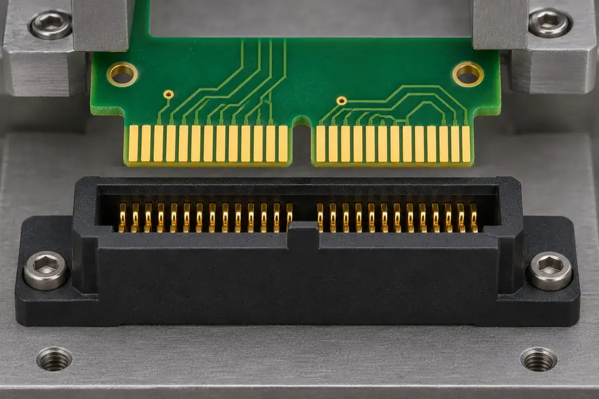
Connector Molding
Relate card edge contact wipe to the gold-finger layout, contact engagement and final insertion stop, rather than using total card travel as the same measurement.
Read article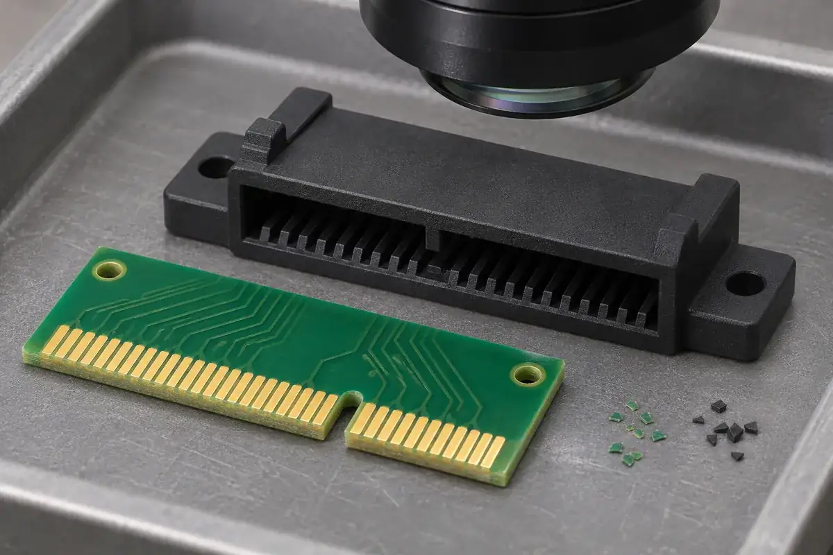
Connector Molding
Investigate debris after card edge insertion by separating PCB edge condition, plastic interference and contact wear, then tracing the location and assembly sequence.
Read article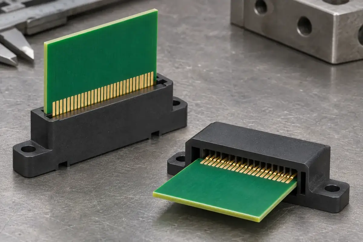
Connector Molding
Compare horizontal and vertical card edge layouts through insertion approach, enclosure clearance, guidance and service removal before choosing a molded housing.
Read article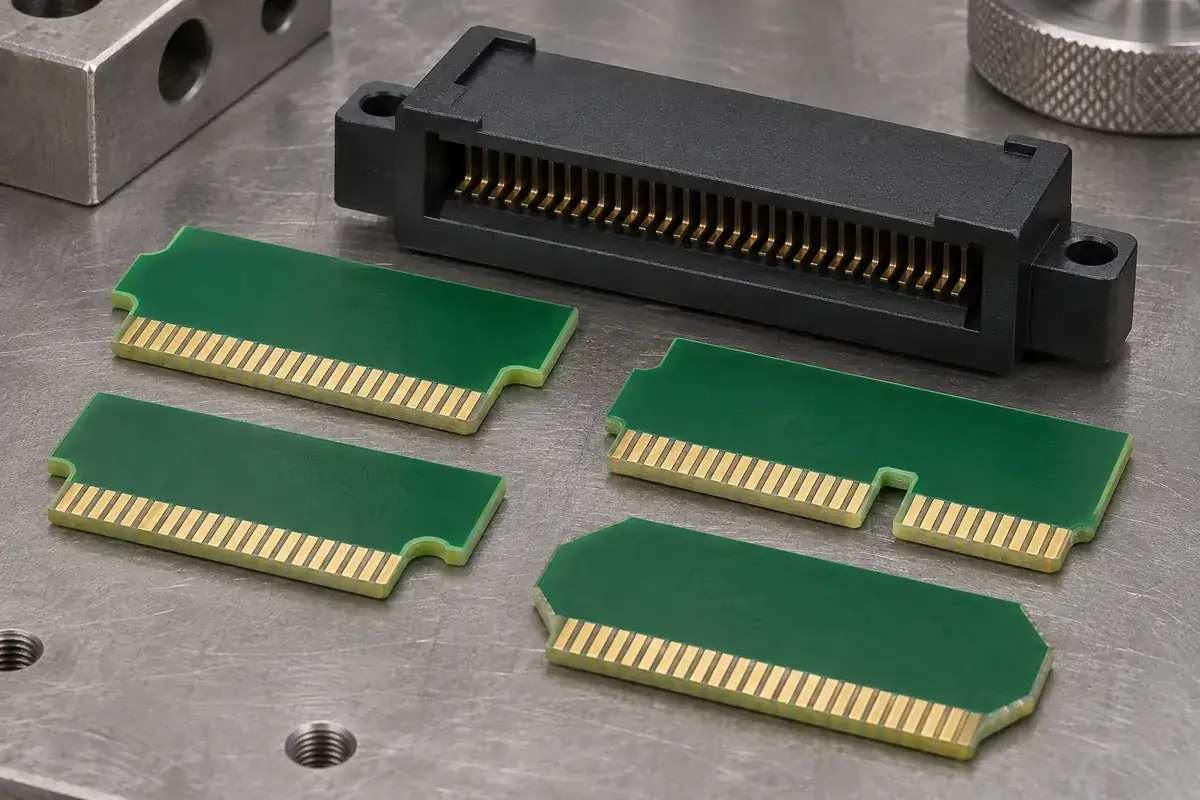
Connector Molding
Design a useful card edge fit coupon by preserving the board thickness, edge finish, pad pattern, notch and references needed for the specific interface check.
Read article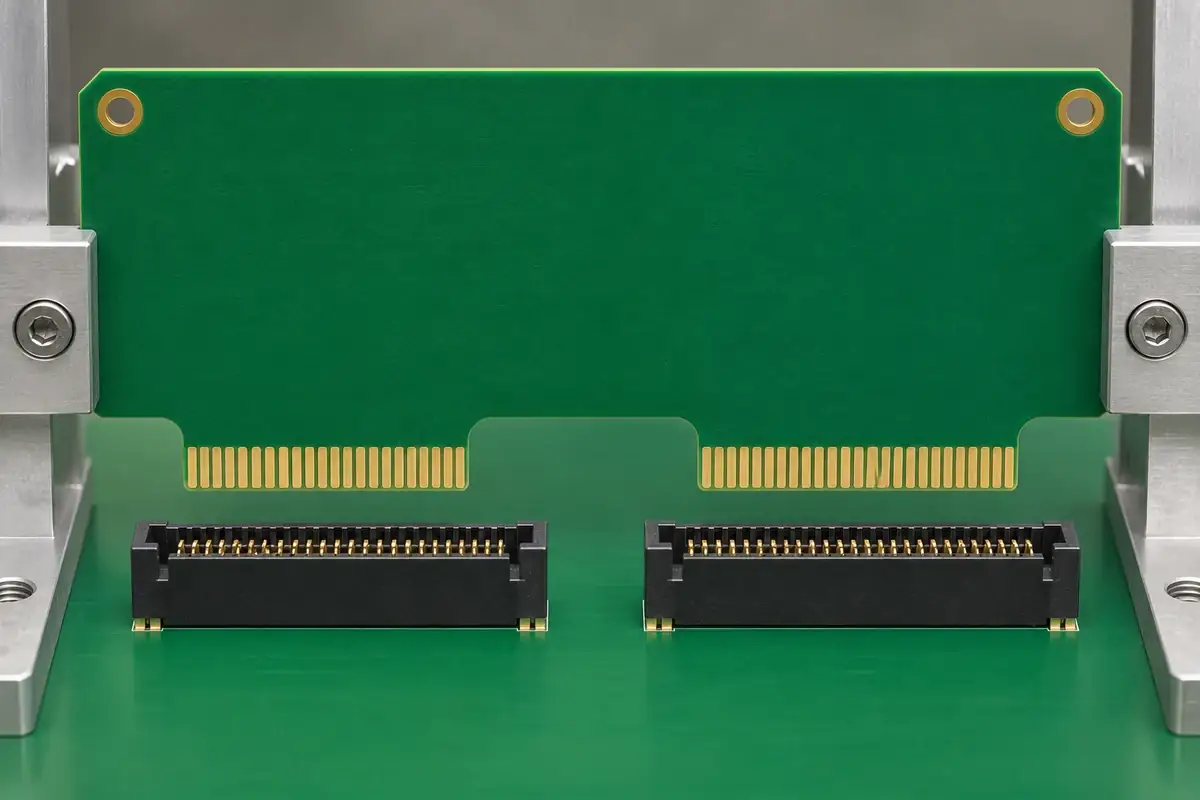
Connector Molding
Review multiple card edge interfaces through shared datums, guide sequence and tolerance accommodation so separate sockets do not demand conflicting board positions.
Read article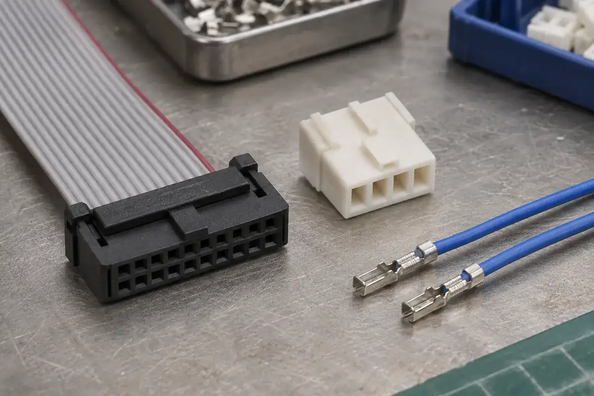
Connector Molding
Compare IDC ribbon-cable and crimp-terminal housings through wire location, termination forces, contact retention and assembly access for custom molded parts.
Read article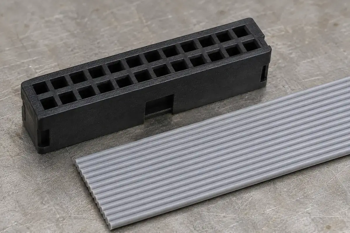
Connector Molding
Understand how ribbon conductor spacing maps to connector contact rows. Review routing, orientation and molded cable guides before changing an IDC housing.
Read article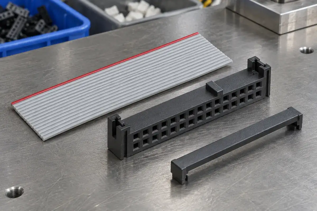
Connector Molding
Review ribbon-cable conductor-one orientation through edge identification, housing marks, polarization and test mapping before releasing an IDC assembly.
Read article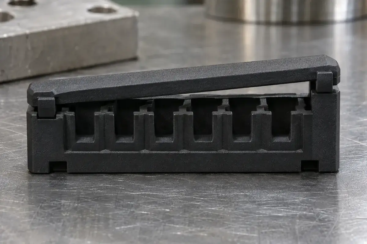
Connector Molding
Investigate uneven IDC cover closure through cable seating, tooling support, latch geometry and molded-part condition before changing the assembly force.
Read article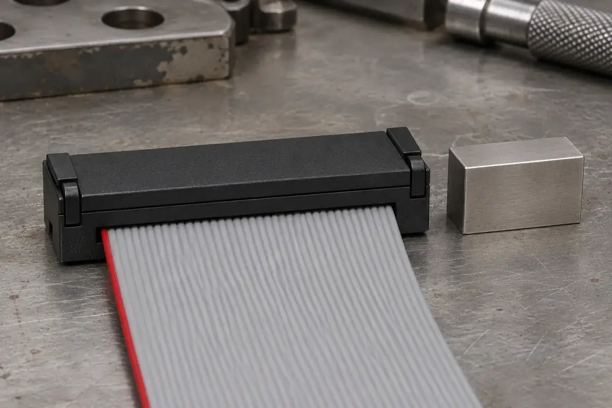
Connector Molding
Define IDC finished height using the correct housing and cover references. Separate latch engagement, tooling travel and electrical termination acceptance.
Read article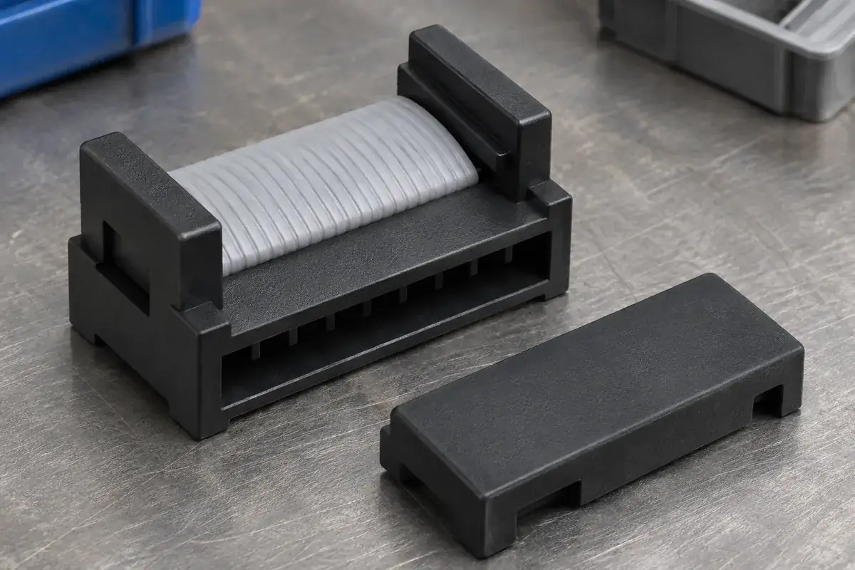
Connector Molding
Review ribbon-cable width, edge margins and conductor location against IDC guide surfaces. Define a loading window without distorting the cable or cover.
Read article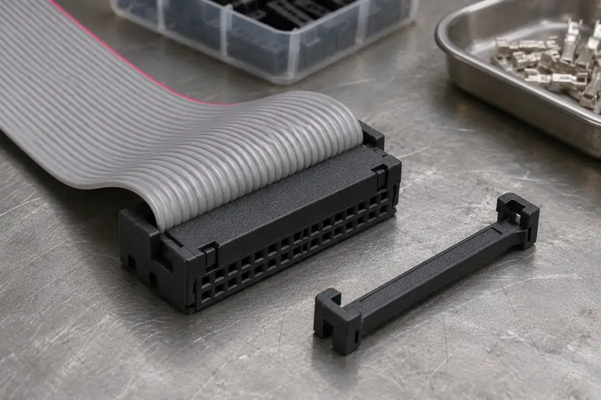
Connector Molding
Follow cable loads through an IDC foldback and strain-relief bar. Review bend space, clamp support and service handling without loading the termination.
Read article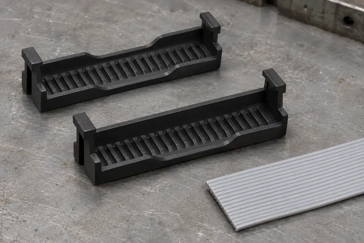
Connector Molding
Compare IDC cable pass-through and end-stop cover layouts for end and intermediate connections. Review routing, loading access and connector-specific limits.
Read article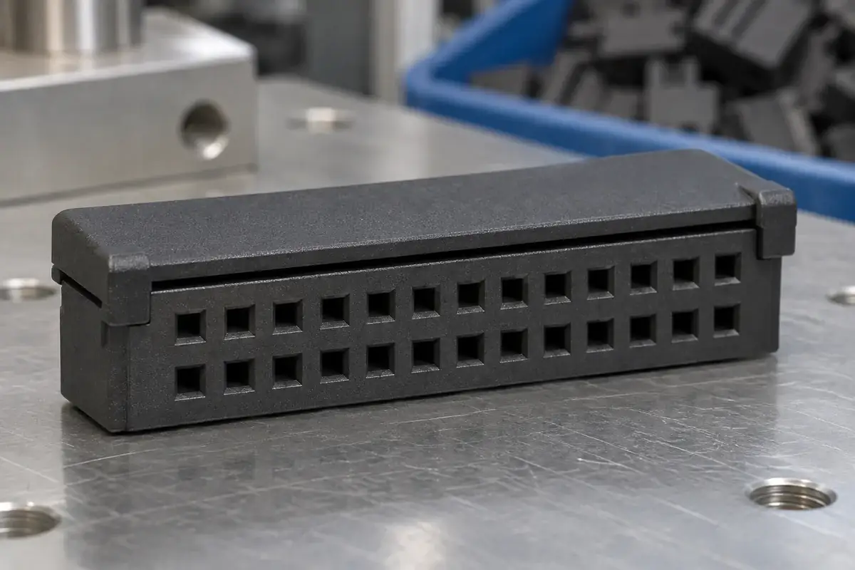
Connector Molding
Review the loose preassembled state of IDC covers through retention, cable access, transport protection and controlled travel to the final termination position.
Read article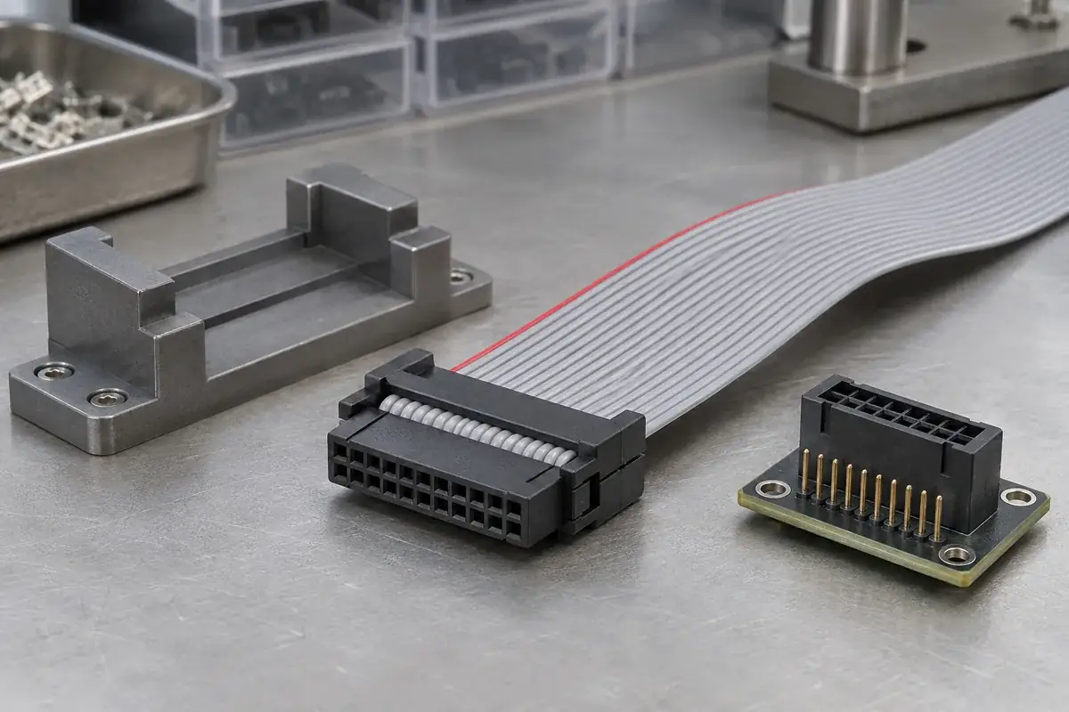
Connector Molding
Separate IDC cover closure, conductor location and electrical verification. Build a traceable inspection plan around the actual cable, contacts and tooling.
Read article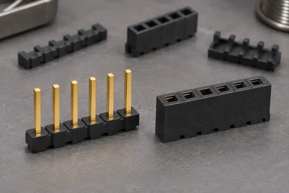
Connector Molding
Compare pin-header bases and socket insulators through contact support, entry guidance, retention and assembly references before specifying a custom molded part.
Read article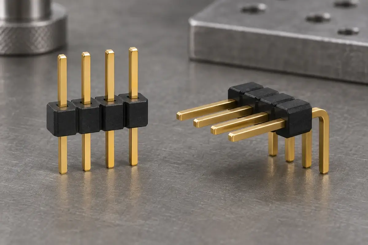
Connector Molding
Review straight and right-angle pin-header bases through force direction, bend support, board seating and fixture access before changing a molded support feature.
Read article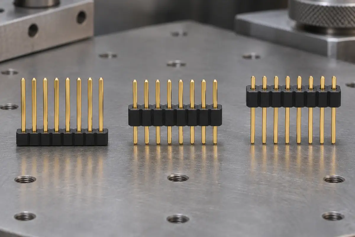
Connector Molding
Understand how pin length, insulator height, body position and board seating combine to determine mating exposure and solder-tail projection in a pin header.
Read article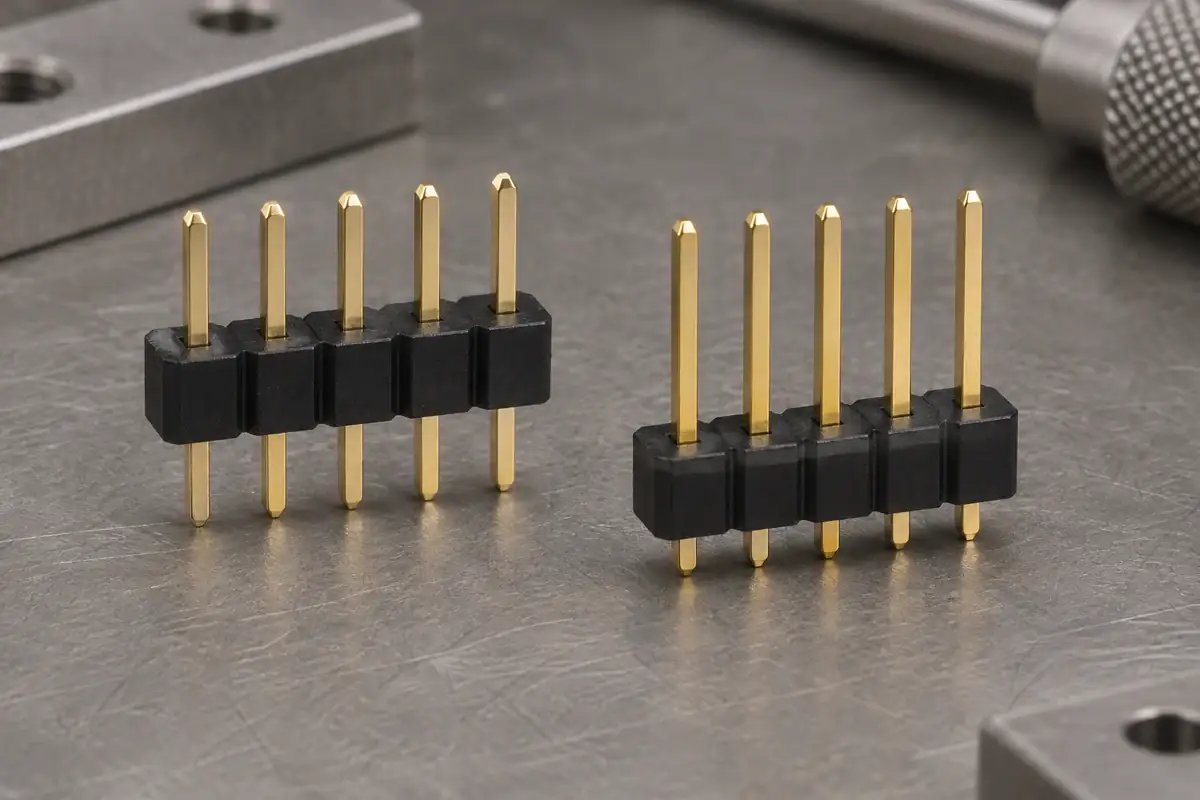
Connector Molding
Diagnose pin-header body movement by separating configured position from unintended drift, then examining retention geometry, assembly support and process exposure.
Read article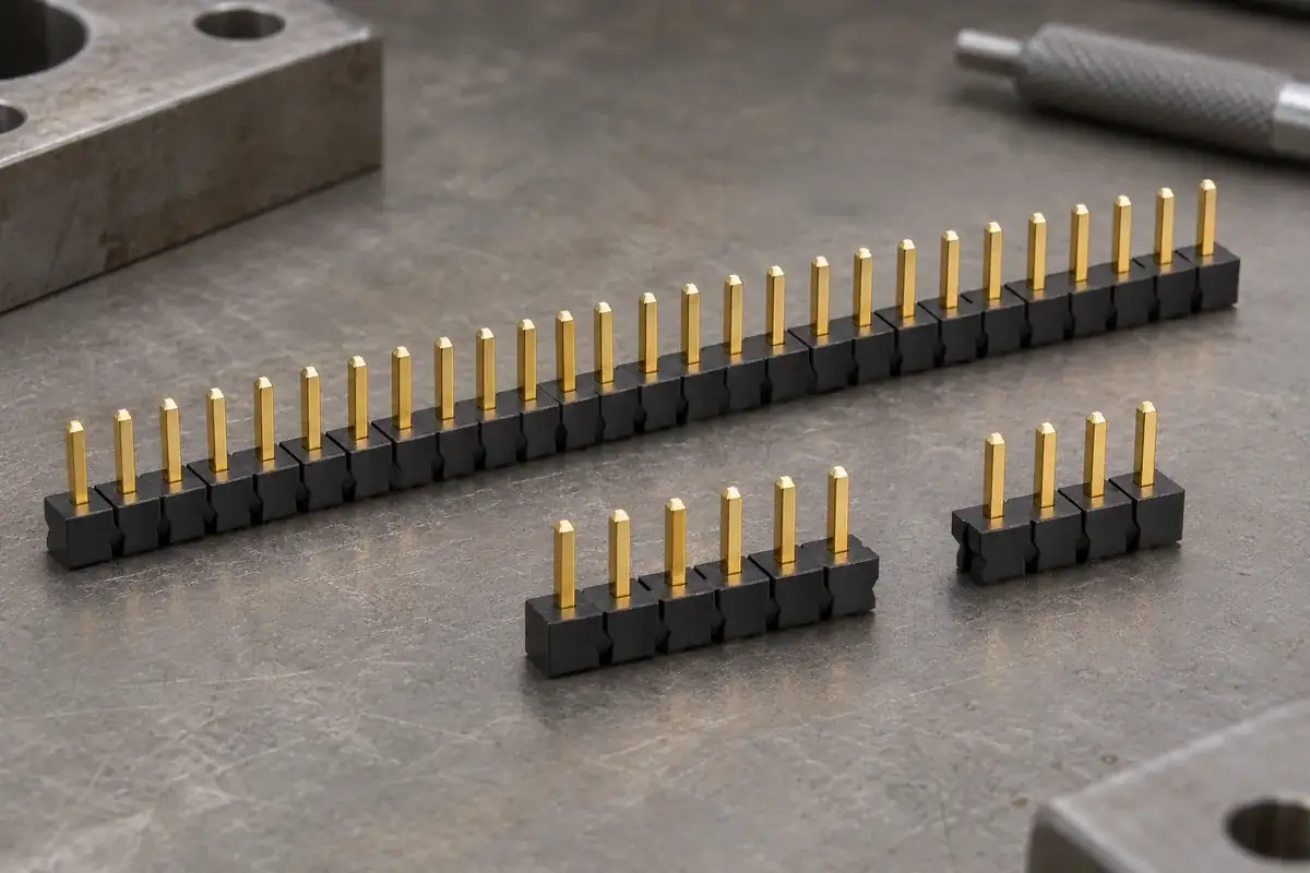
Connector Molding
Trace cracks after cutting a breakaway pin header through notch placement, remaining end-wall thickness, fixture support and inspection of the separated section.
Read article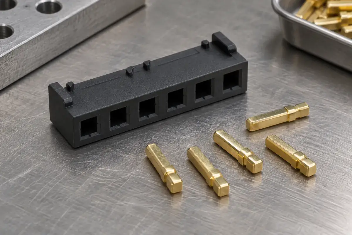
Connector Molding
Investigate square-pin orientation, hole corners, retention features and insertion support before changing a cracked pin-header insulator or its material.
Read article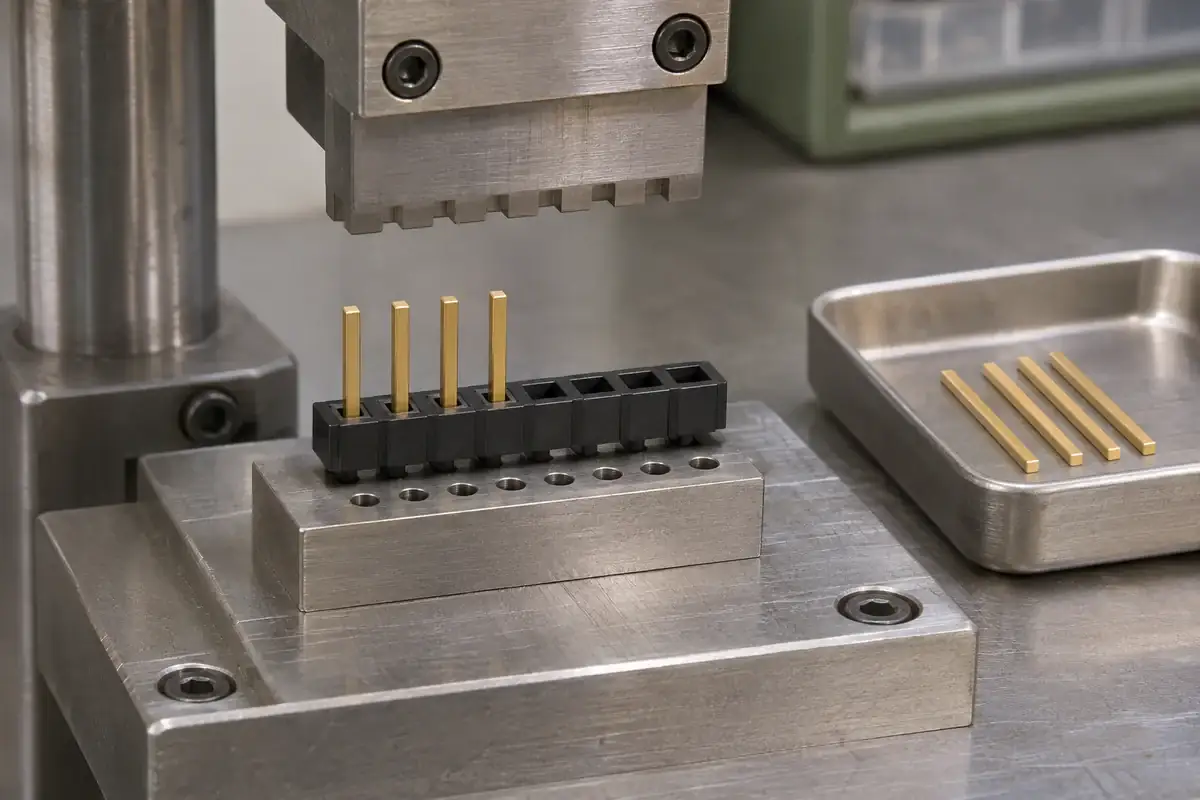
Connector Molding
Plan pin-header insertion tooling around the load path, supported plastic faces, tail clearance and seating reference rather than pressing against thin edges.
Read article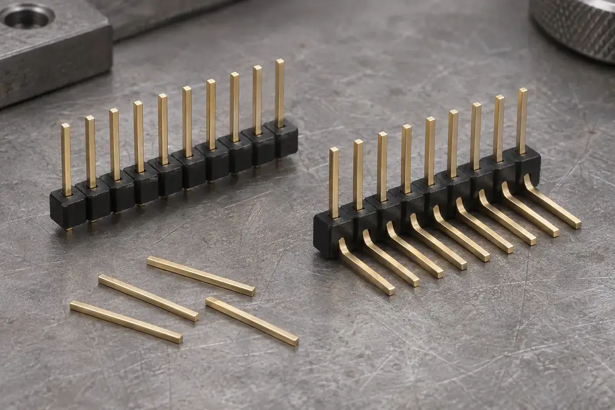
Connector Molding
Compare pin forming before and after base installation through tooling access, reaction forces, locating references and final right-angle header geometry.
Read article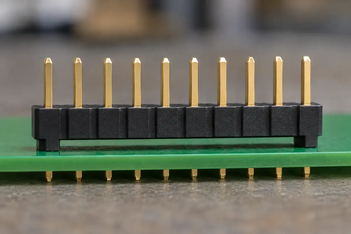
Connector Molding
Review pin-header board clearance through molded feet, solder-tail projection, joint visibility and cleaning paths without treating one gap as a universal rule.
Read article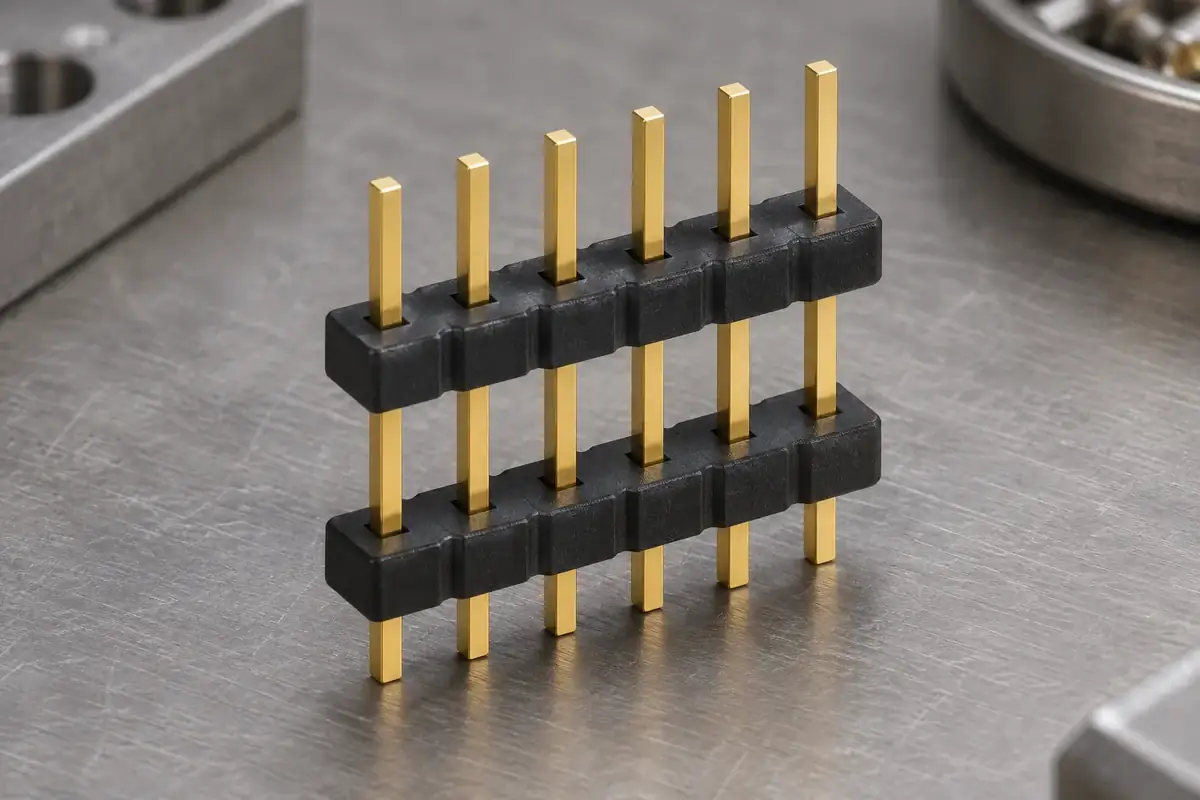
Connector Molding
Define two insulator positions on a shared pin array using functional references, controlled support and free-state inspection of alignment and exposed lengths.
Read article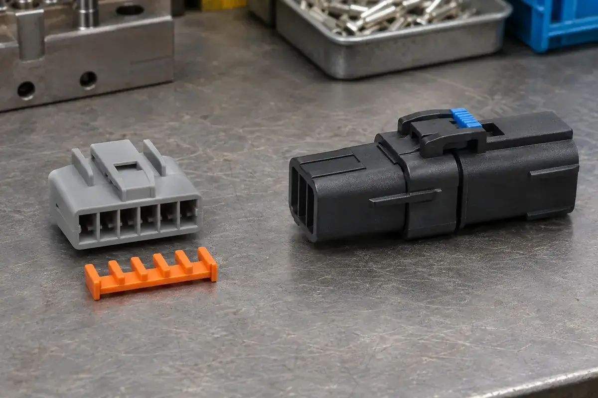
Connector Molding
Understand how TPA retains terminals and CPA supports connector mating, then define the plastic interfaces, assembly states and checks each design needs.
Read article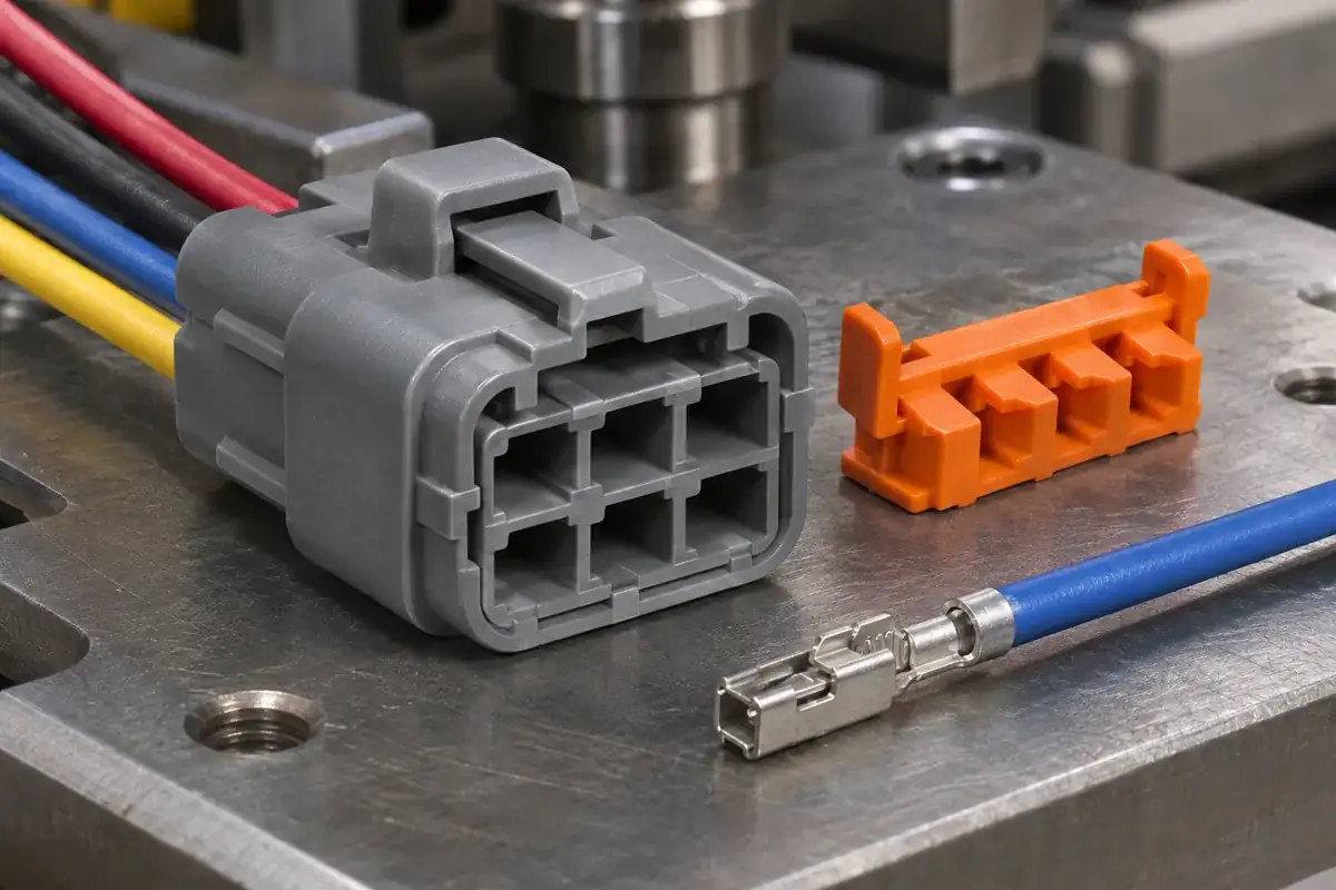
Connector Molding
Investigate a closed TPA with an unseated terminal by checking component compatibility, seating references, lock travel, damage and assembly conditions.
Read article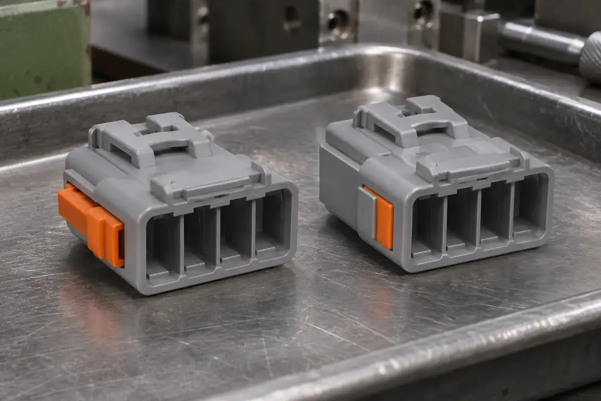
Connector Molding
Plan connector secondary-lock assembly from the supplied pre-lock state through contact loading, final locking, mating and controlled service release.
Read article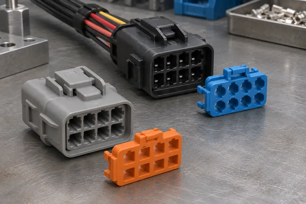
Connector Molding
Compare front- and rear-loading terminal locks through contact access, wire population, fixtures and service space before choosing a connector layout.
Read article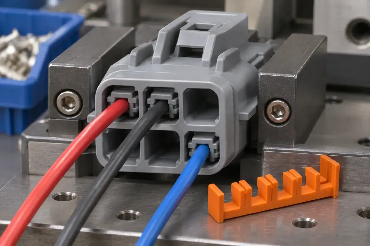
Connector Molding
Review partly populated connector housings through TPA engagement, empty-cavity treatment, sealing plugs, inspection and controlled harness variants.
Read article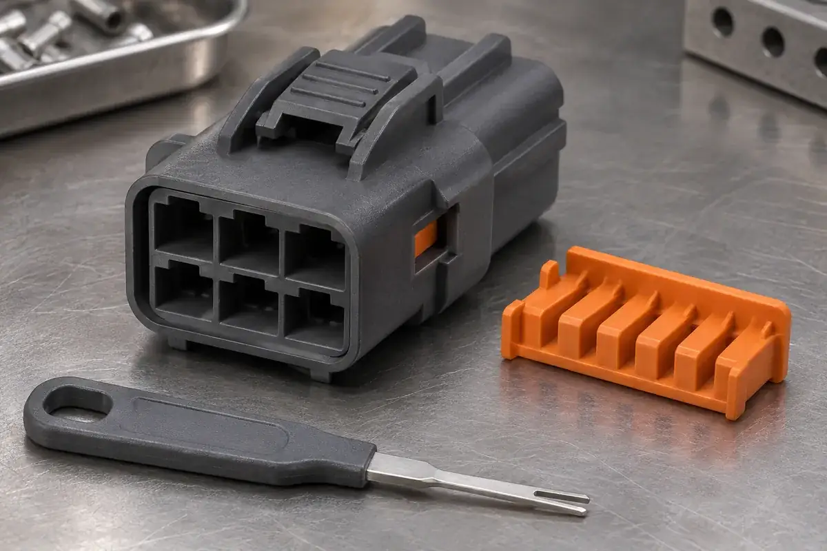
Connector Molding
Reduce secondary-lock damage during connector repair by reviewing the release sequence, tool approach, housing support and condition of the locking features.
Read article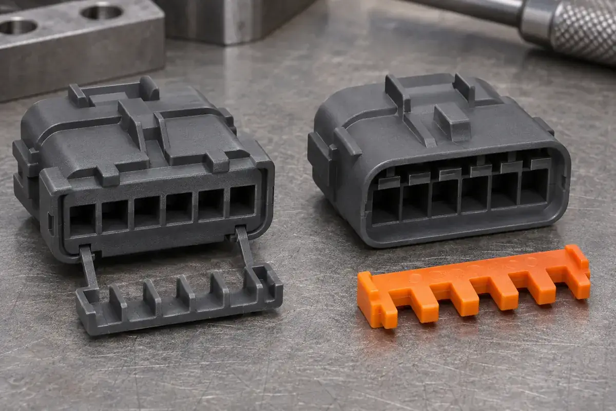
Connector Molding
Compare integrated and separate TPA concepts through assembly sequence, material needs, molding constraints, repairability and component supply requirements.
Read article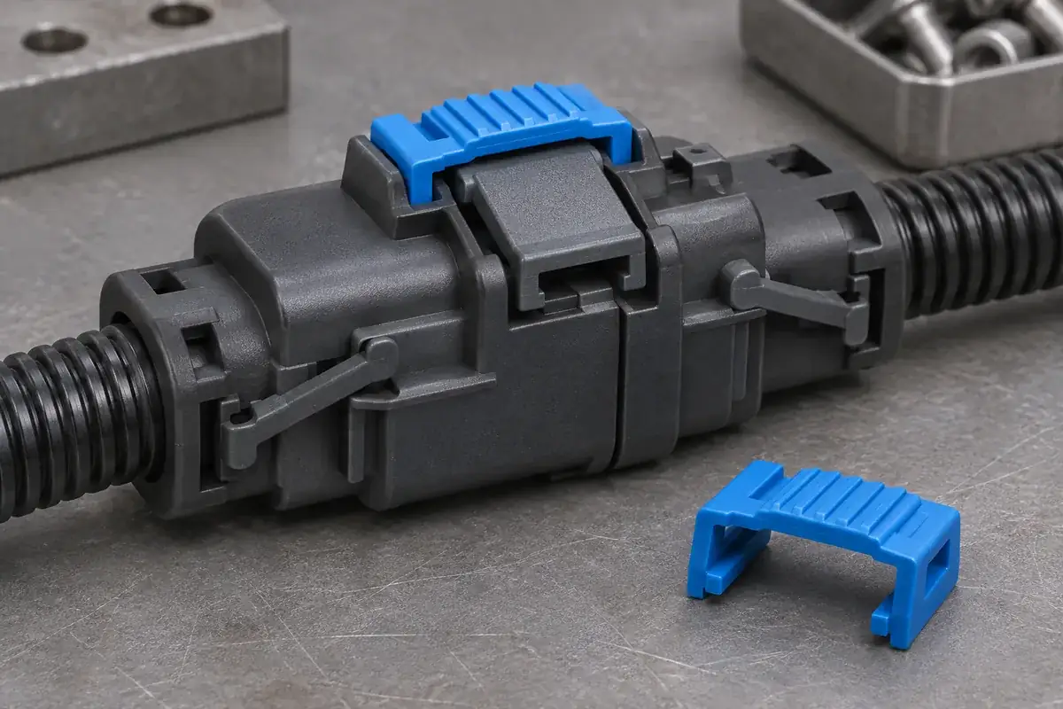
Connector Molding
Use CPA color as a locating aid, then define the mechanical position, viewing direction and inspection evidence needed to confirm connector-lock engagement.
Read article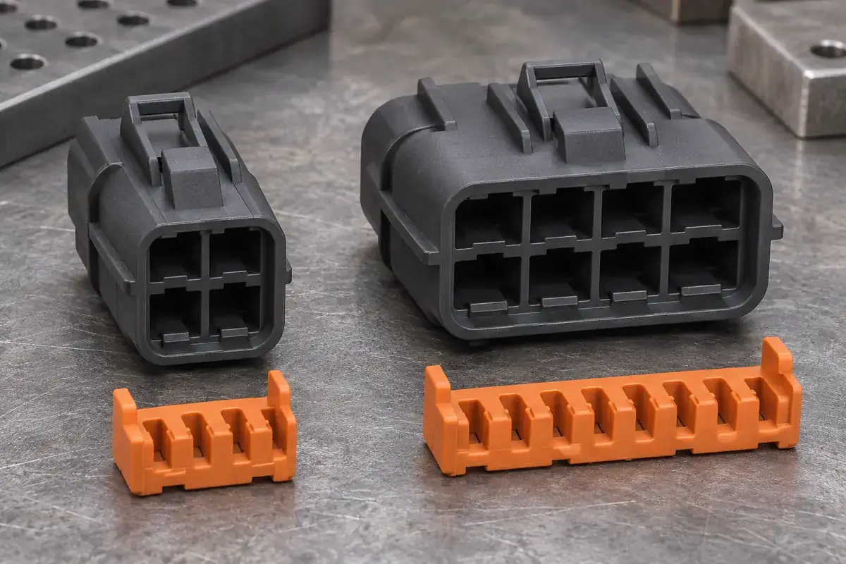
Connector Molding
Evaluate a shared connector secondary lock by comparing terminal pitch, guide rails, stops, latch interfaces, assembly access and revision control across housings.
Read article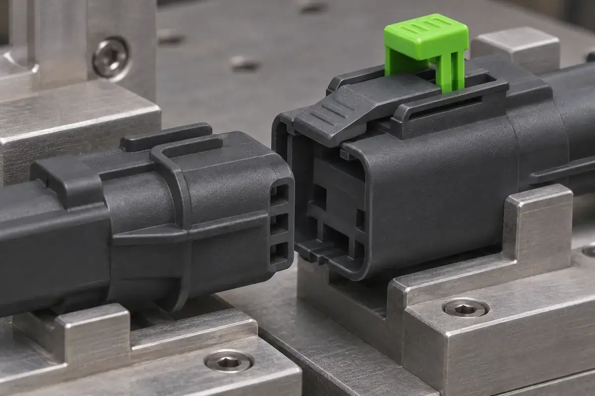
Connector Molding
Review CPA interlocks through partial mating, primary-latch movement, final stops and tolerance variation before treating a closed lock as mating confirmation.
Read article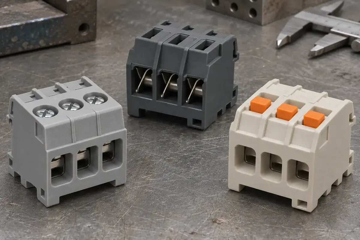
Connector Molding
Compare terminal-block housing requirements for screw, spring and push-in connections, including clamp support, wire guidance and operating access.
Read article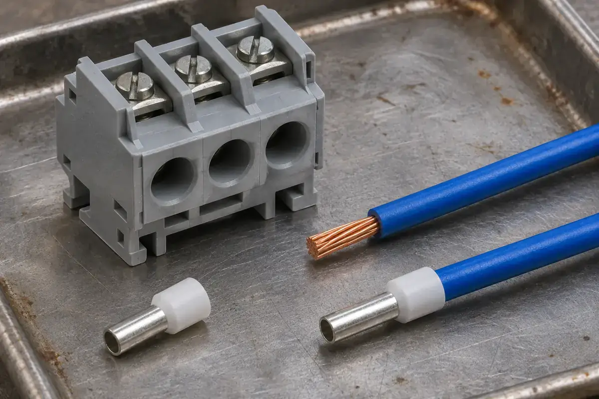
Connector Molding
Trace terminal-block wire-entry problems through insulation diameter, ferrule shape, strip length and clamp depth before changing the plastic housing.
Read article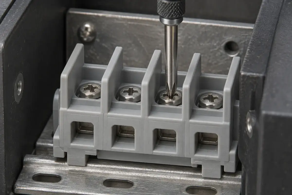
Connector Molding
Coordinate terminal-block screwdriver paths, shaft clearance, operating angles and insulating guard walls within the actual equipment installation.
Read article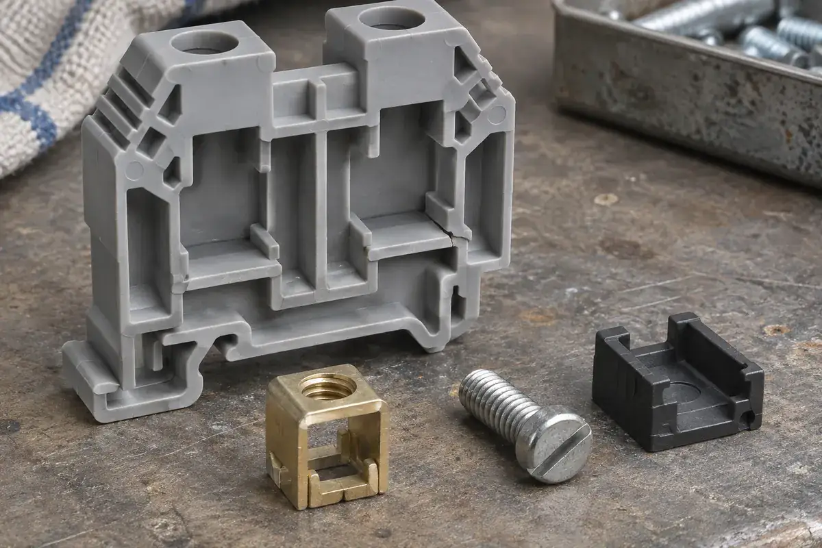
Connector Molding
Investigate terminal-block housing cracks by following screw forces through metal cages, plastic supports and mounting points before changing resin.
Read article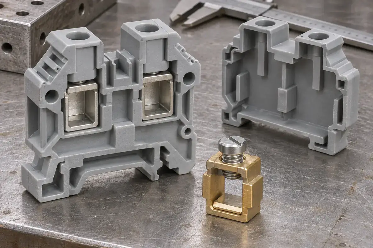
Connector Molding
Design terminal-block insert location around broad flats, support surfaces, assembly clearance and operating forces so metal parts retain their orientation.
Read article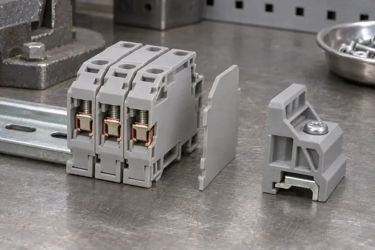
Connector Molding
Understand when a terminal block row needs an end plate, how it differs from a rail clamp, and which molded interfaces deserve review before tooling.
Read article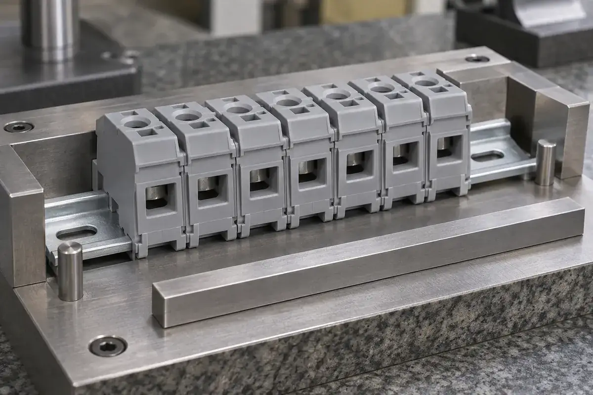
Connector Molding
Learn why a long modular terminal block row can drift even when individual housings pass inspection, and how to review pitch, joining fit and mounting.
Read article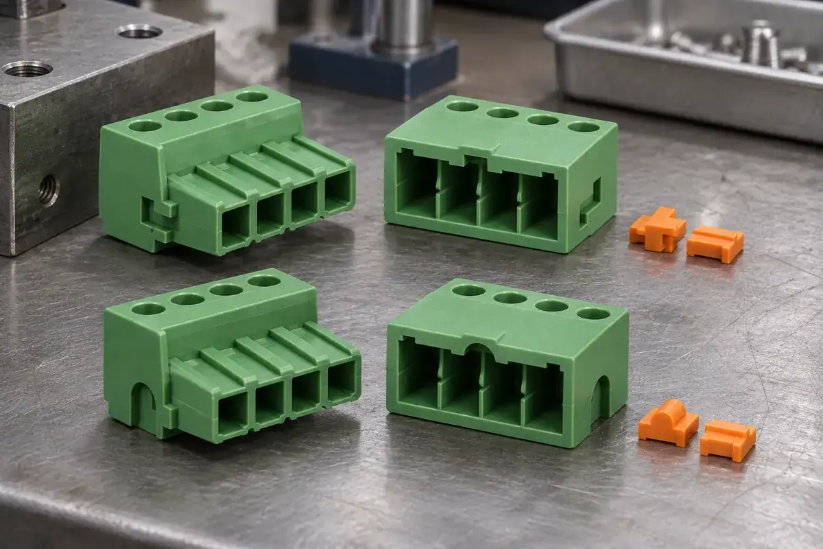
Connector Molding
Plan mechanical coding and readable circuit identification for pluggable terminal blocks, including wrong-pair checks, assembly sequence and service changes.
Read article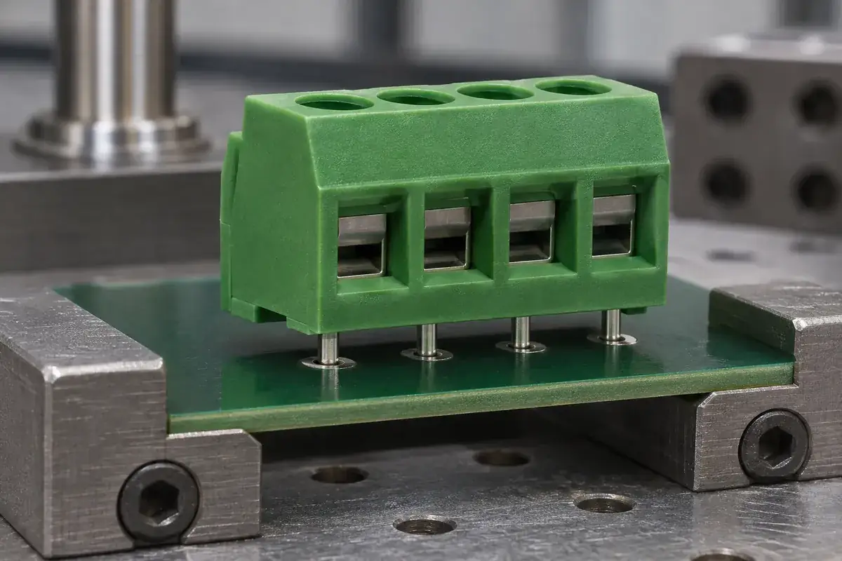
Connector Molding
Review terminal block standoffs, underside cavities and board clearance for cleaning and drying, while keeping resin compatibility and process validation explicit.
Read article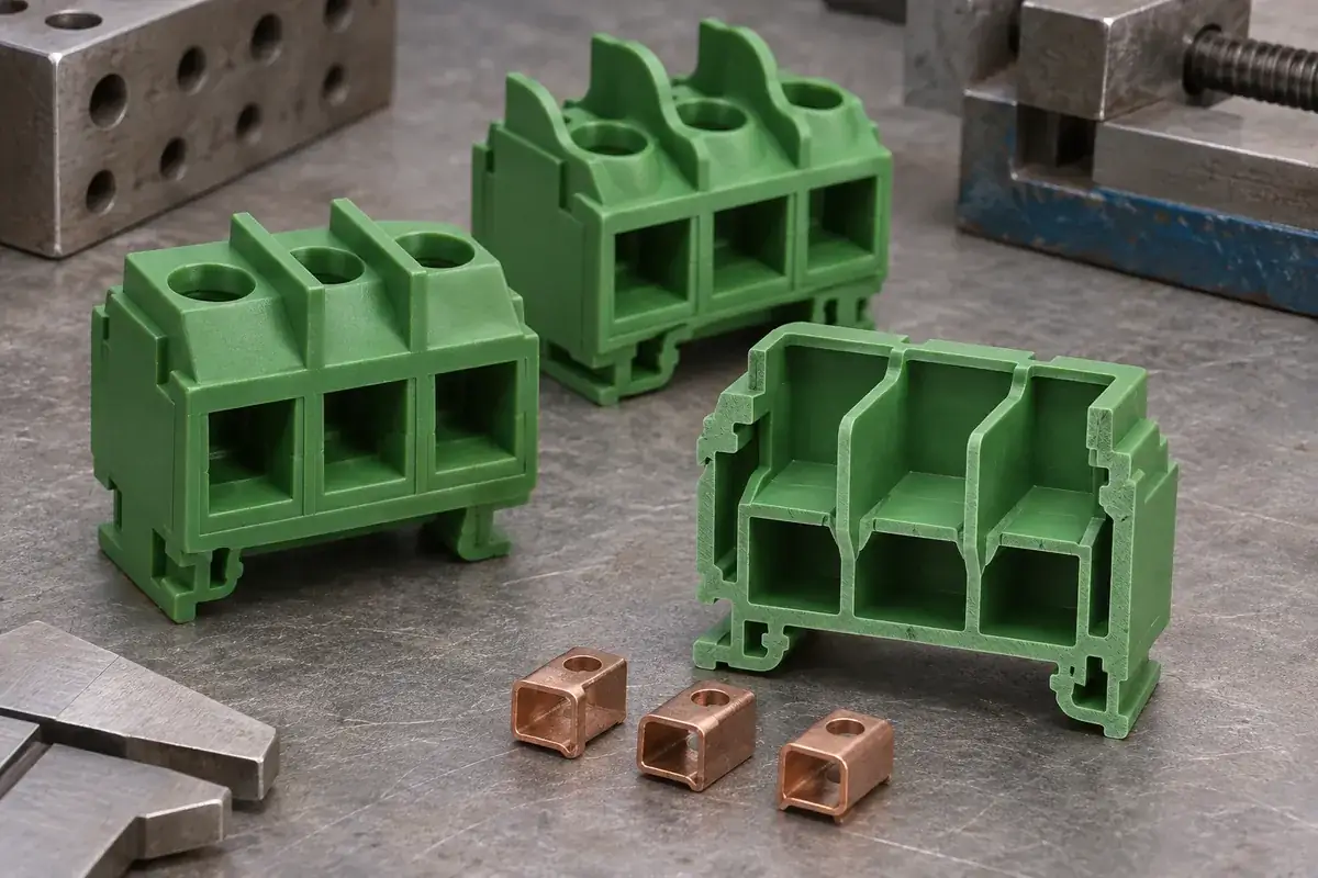
Connector Molding
Understand how terminal block barriers affect air and surface paths, what CTI describes, and which assembly details must be reviewed before assigning ratings.
Read article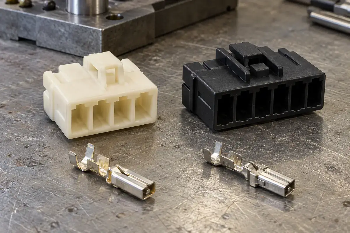
Connector Molding
Compare wire-to-board housing types through termination, mating access, locking and harness routing before defining a custom molded component.
Read article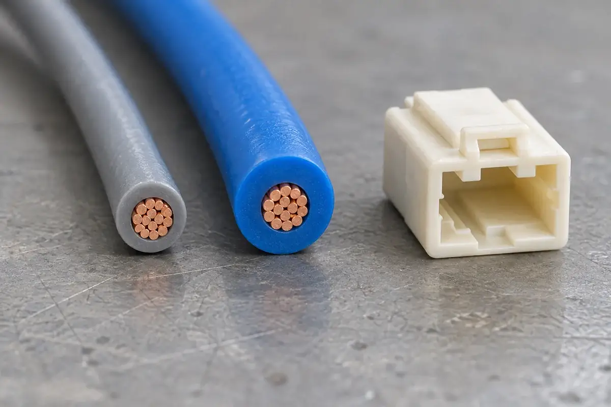
Connector Molding
Understand why equal-AWG wires can fit connector housings differently. Review insulation diameter, crimp envelopes and rear-entry geometry together.
Read article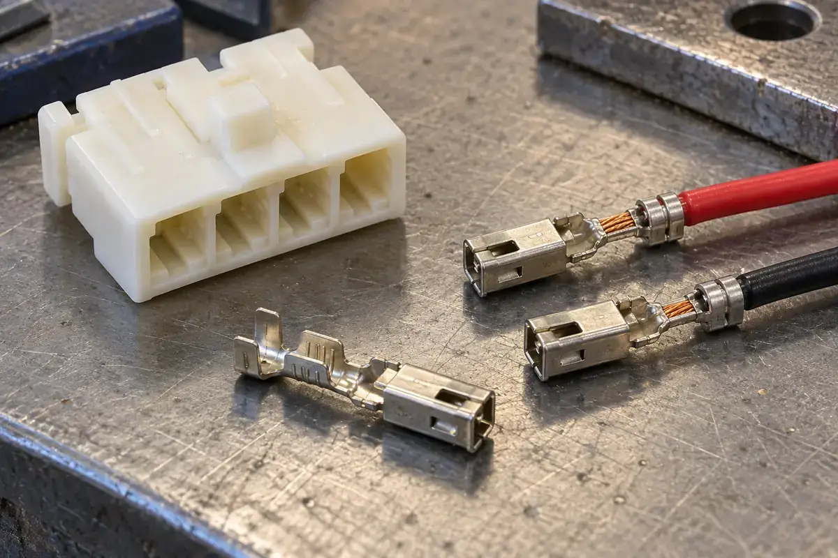
Connector Molding
Trace crimp-terminal insertion interference through orientation, formed crimp wings, contact straightness and housing entry geometry before changing tooling.
Read article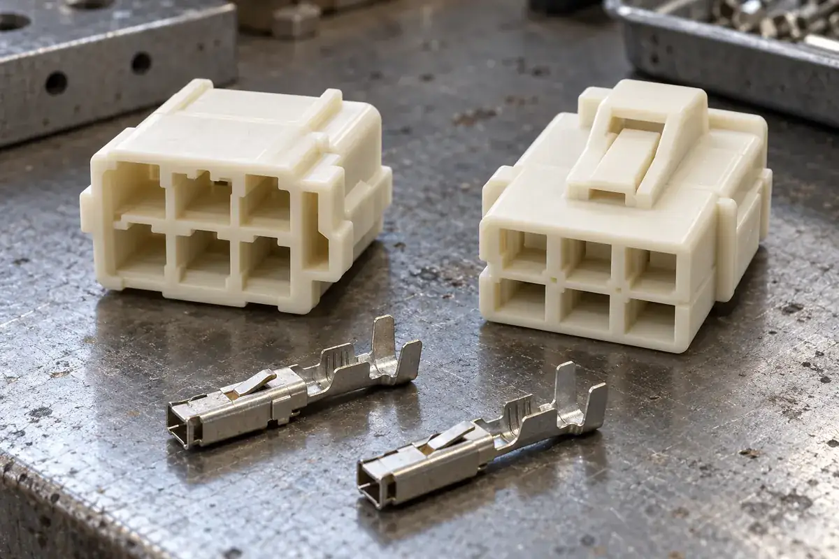
Connector Molding
Separate terminal orientation, cavity numbering and mating polarization. Design wire-to-board housing guides around the actual contact loading sequence.
Read article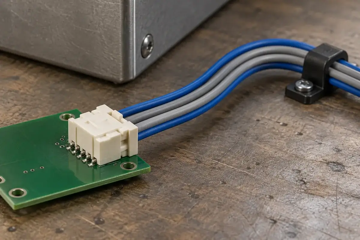
Connector Molding
Plan wire-to-board harness exits around free wire length, bend direction, support points and latch access so routing loads do not concentrate at the connector.
Read article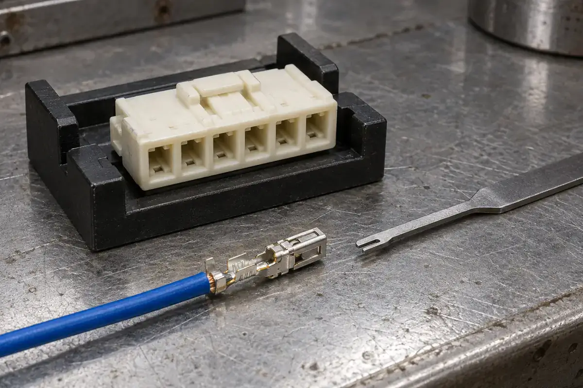
Connector Molding
Review the release window, extraction tool path and wire access of a wire-to-board housing before a repair turns into a damaged contact or locking feature.
Read article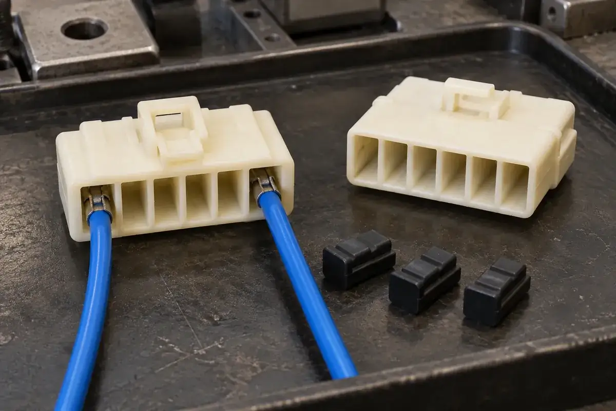
Connector Molding
Plan partially populated wire-to-board housings by separating circuit selection, assembly blocking and sealing, including cavity-plug fit and service access.
Read article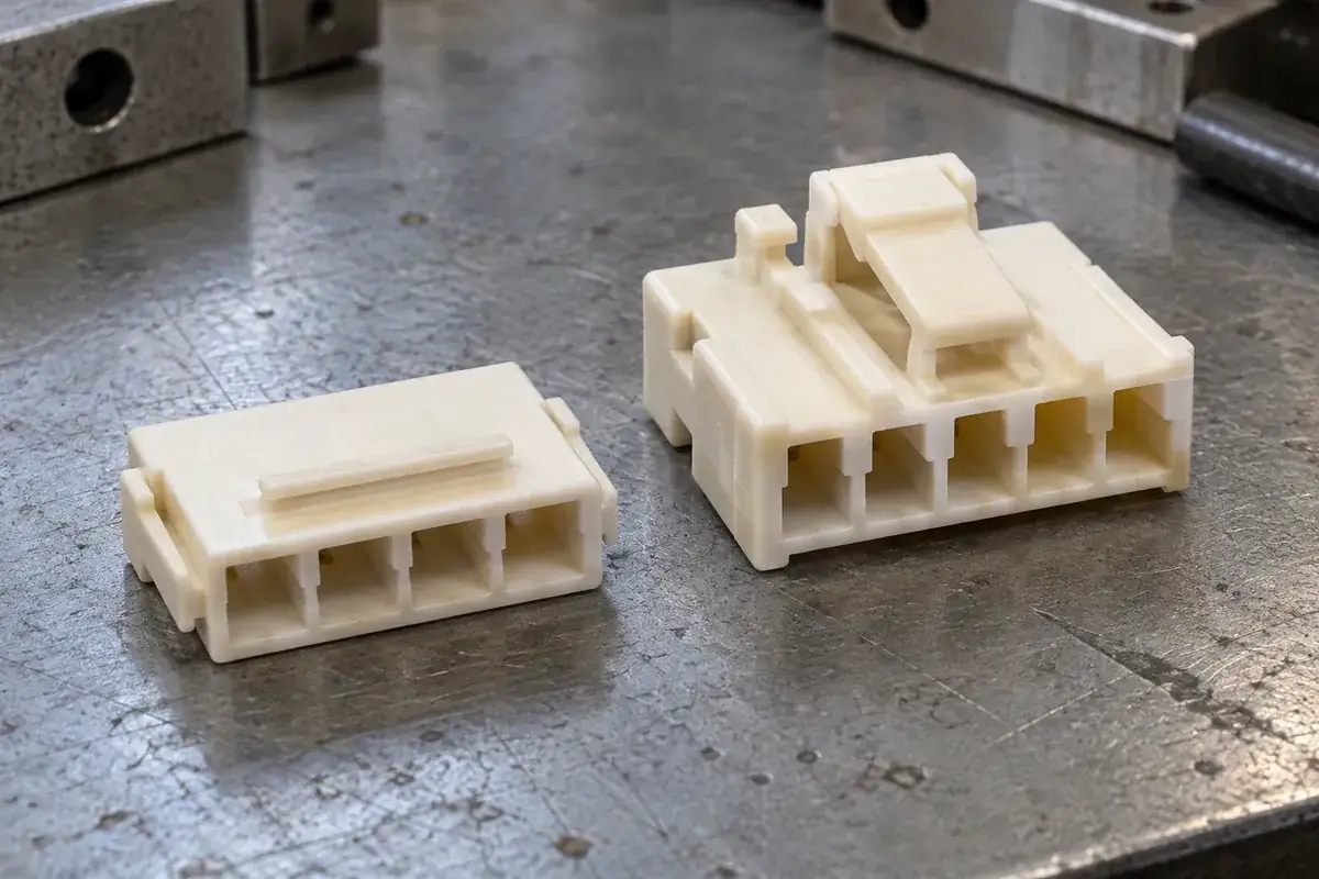
Connector Molding
Compare friction retention and positive latching through harness loads, operating access and service needs before choosing a custom wire-to-board housing interface.
Read article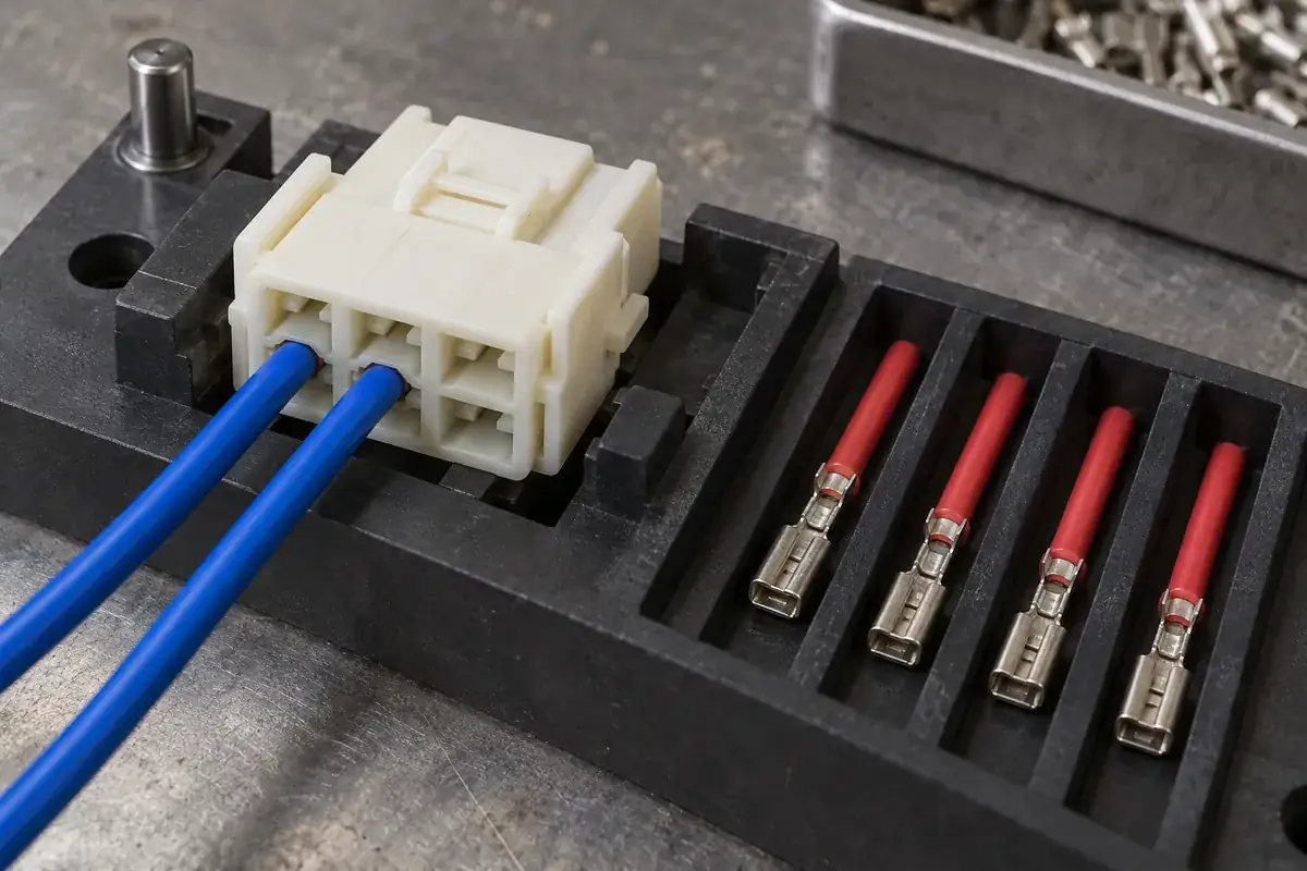
Connector Molding
Plan wire-to-board terminal loading around changing cavity access, wire routing and confirmation steps so a populated harness remains practical to assemble.
Read article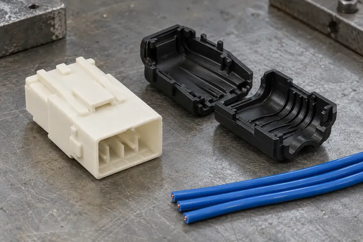
Connector Molding
Review wire exits, crimp clearance, closure paths and load transfer when designing rear covers for custom wire-to-board connector housings.
Read article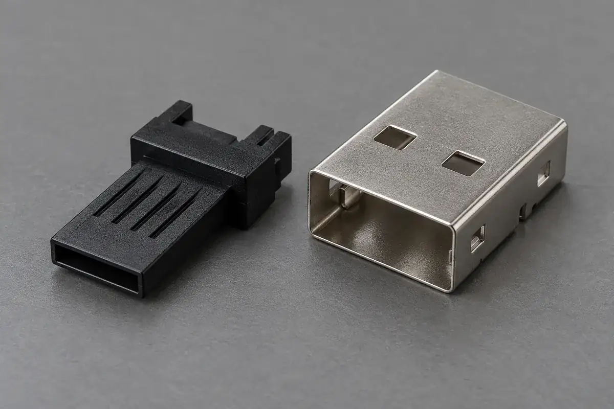
Connector Molding
Define the molded USB tongue, terminal carrier and retaining parts separately from the complete connector, then connect their drawings to assembly requirements.
Read article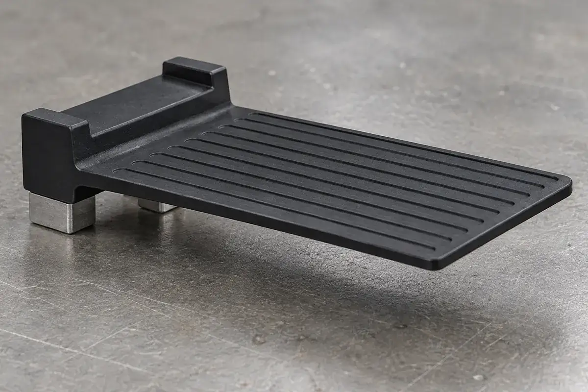
Connector Molding
Understand how molding flow, root geometry and fixture support affect USB insulating tongue flatness, and separate free-state inspection from assembly checks.
Read article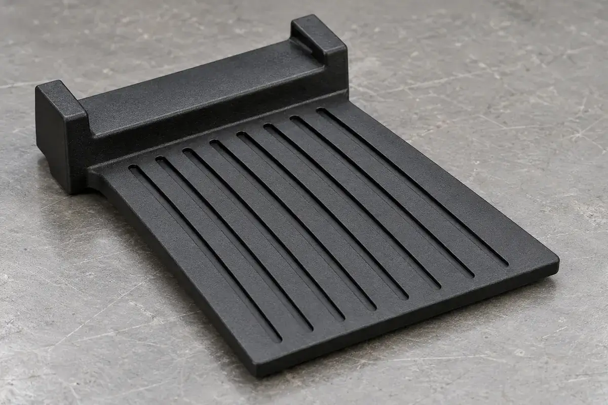
Connector Molding
Trace contact-slot flash to the molding interface, distinguish it from short fill and damage, and define inspection around the terminal installation path.
Read article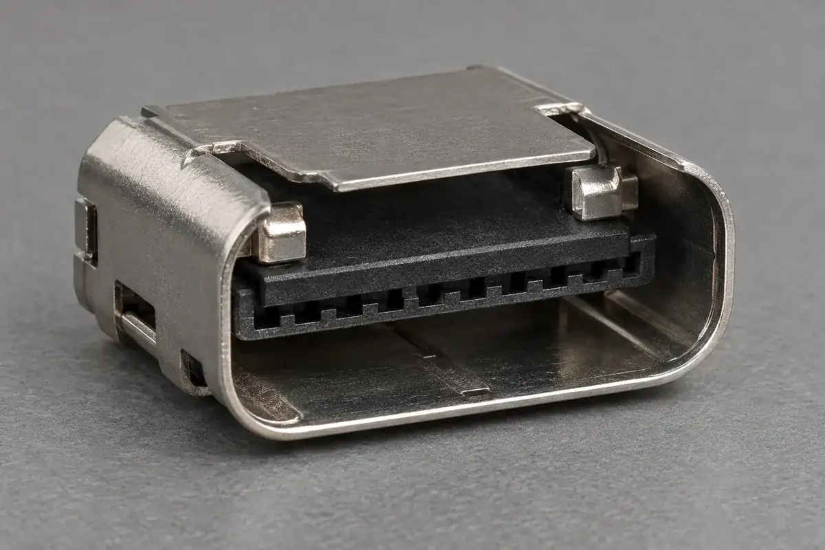
Connector Molding
Connect tongue position to carrier shoulders, shell stops and inspection datums so a USB plastic component can be evaluated in its intended assembly.
Read article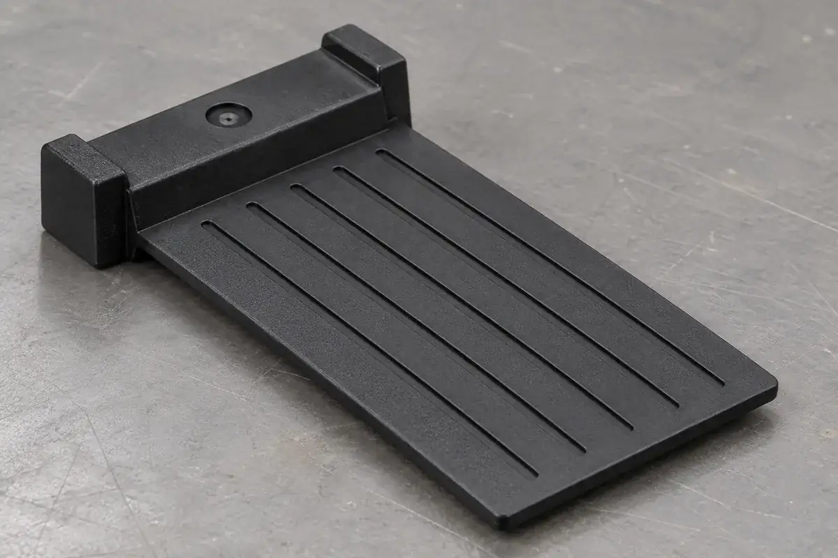
Connector Molding
Place the gate and its remaining witness around the USB insulator’s flow path, shell seating surfaces and contact channels, with controlled trimming access.
Read article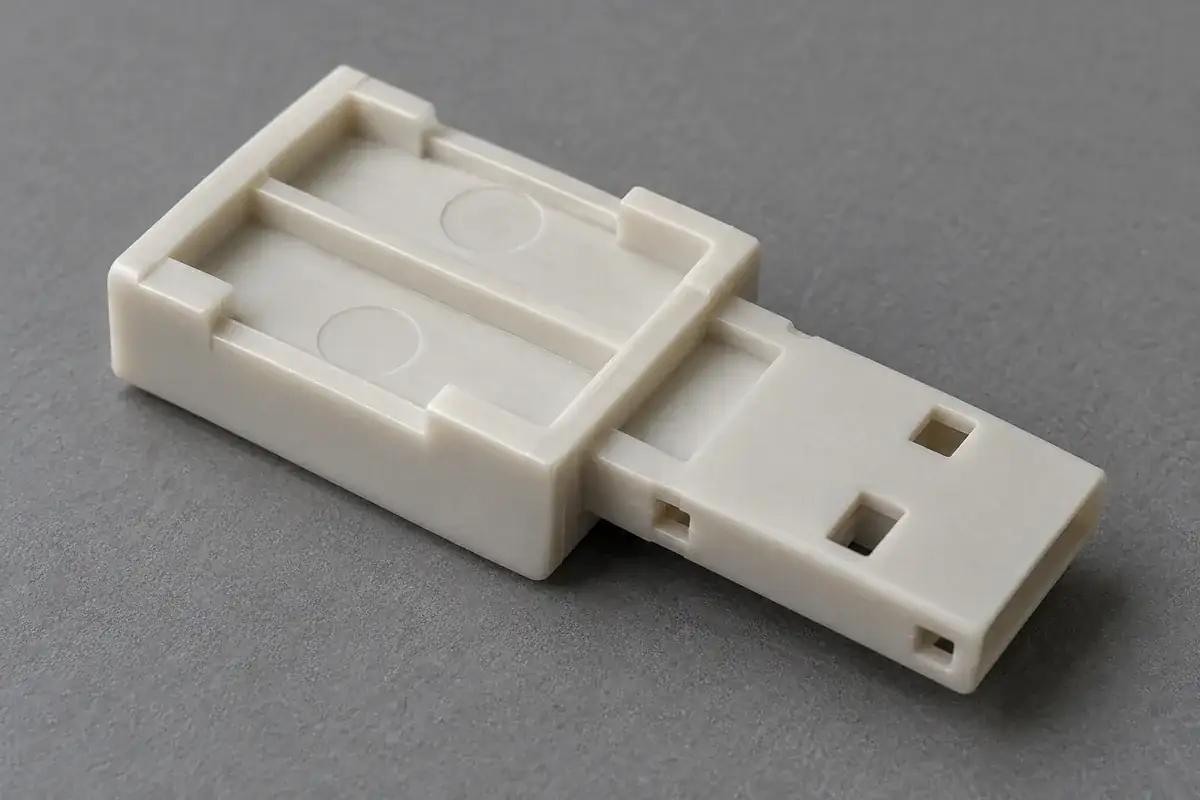
Connector Molding
Control ejector witnesses and release forces on USB insulating tongues by relating pin locations, support regions and surface acceptance to assembly function.
Read article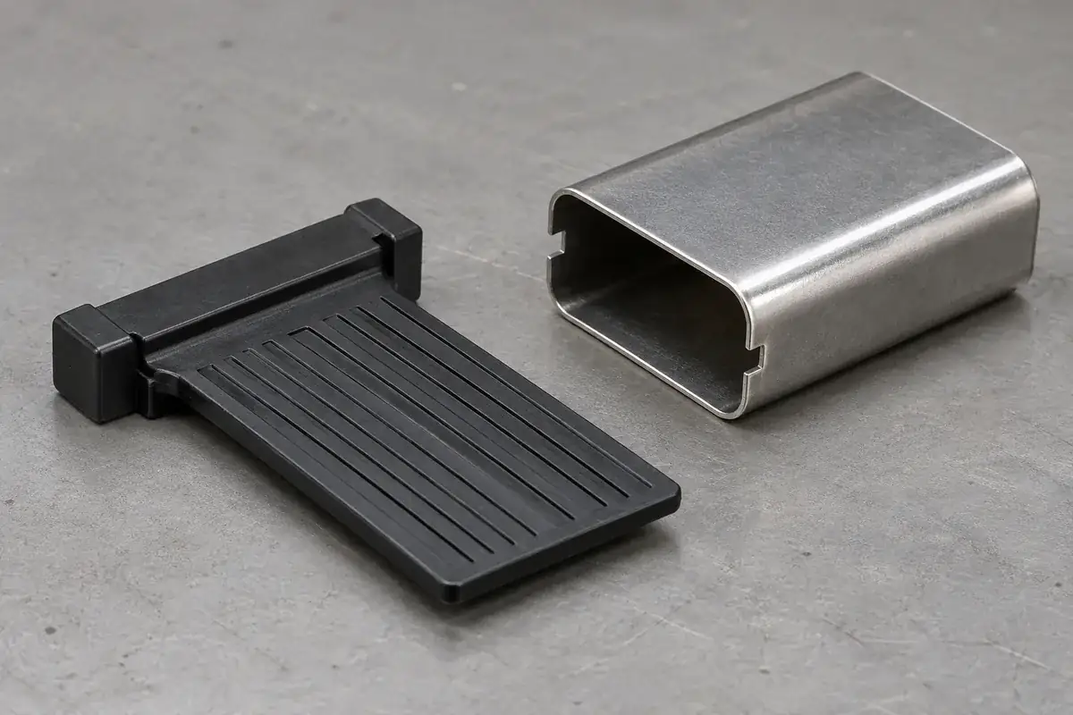
Connector Molding
Diagnose scraping, cracking and deformation when a USB insulator enters its shell by reviewing the lead-in, support, insertion path and component evidence.
Read article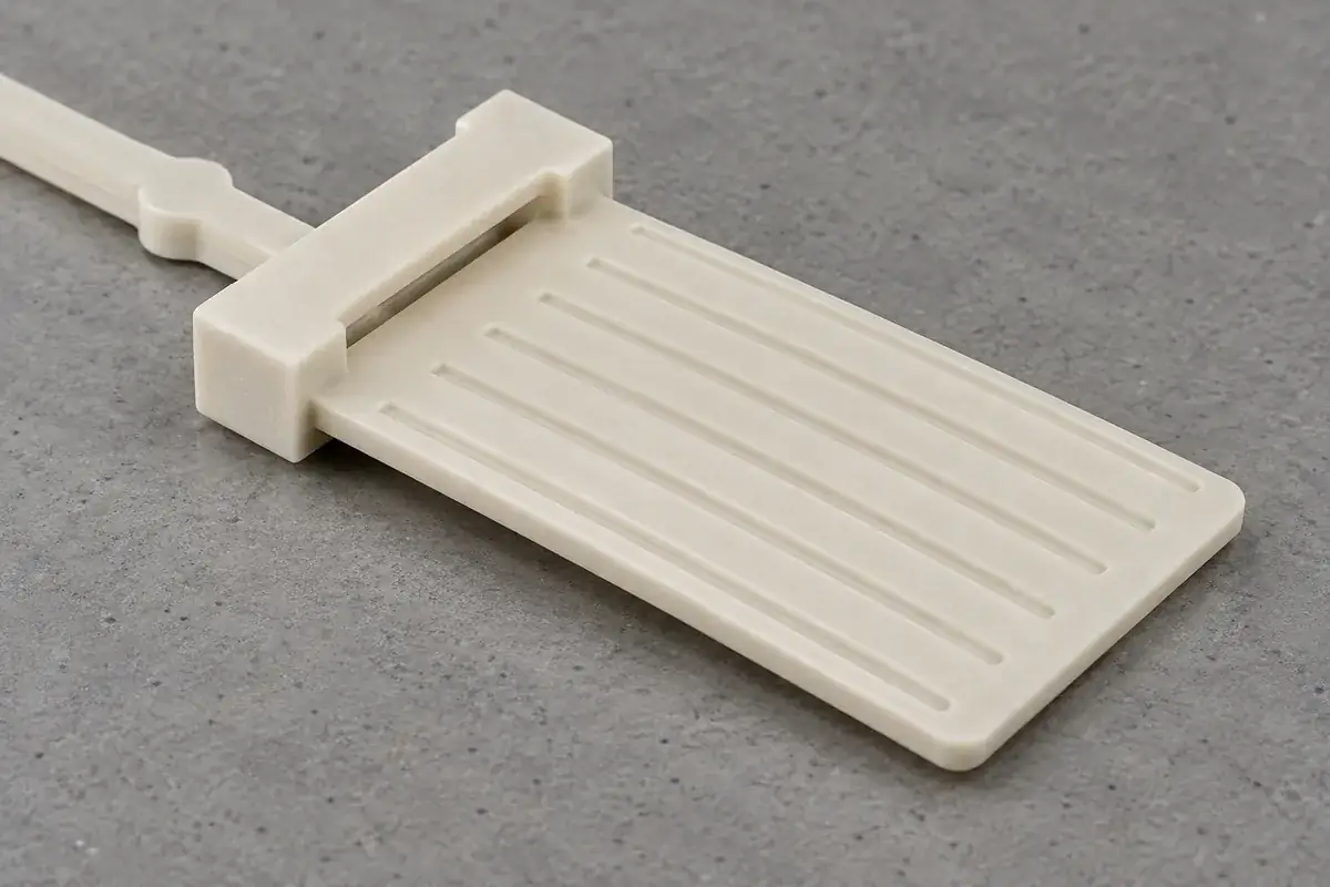
Connector Molding
Review weld-line location in a molded USB tongue against its flow path, thin bridges and assembly loads, then plan samples that test the actual configuration.
Read article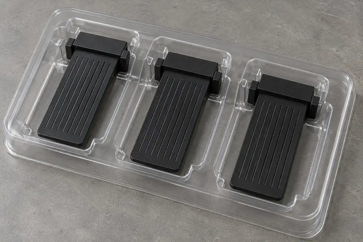
Connector Molding
Protect molded USB tongues and contact channels through trimming, transfer and packing, with cleanliness criteria tied to the component and assembly process.
Read article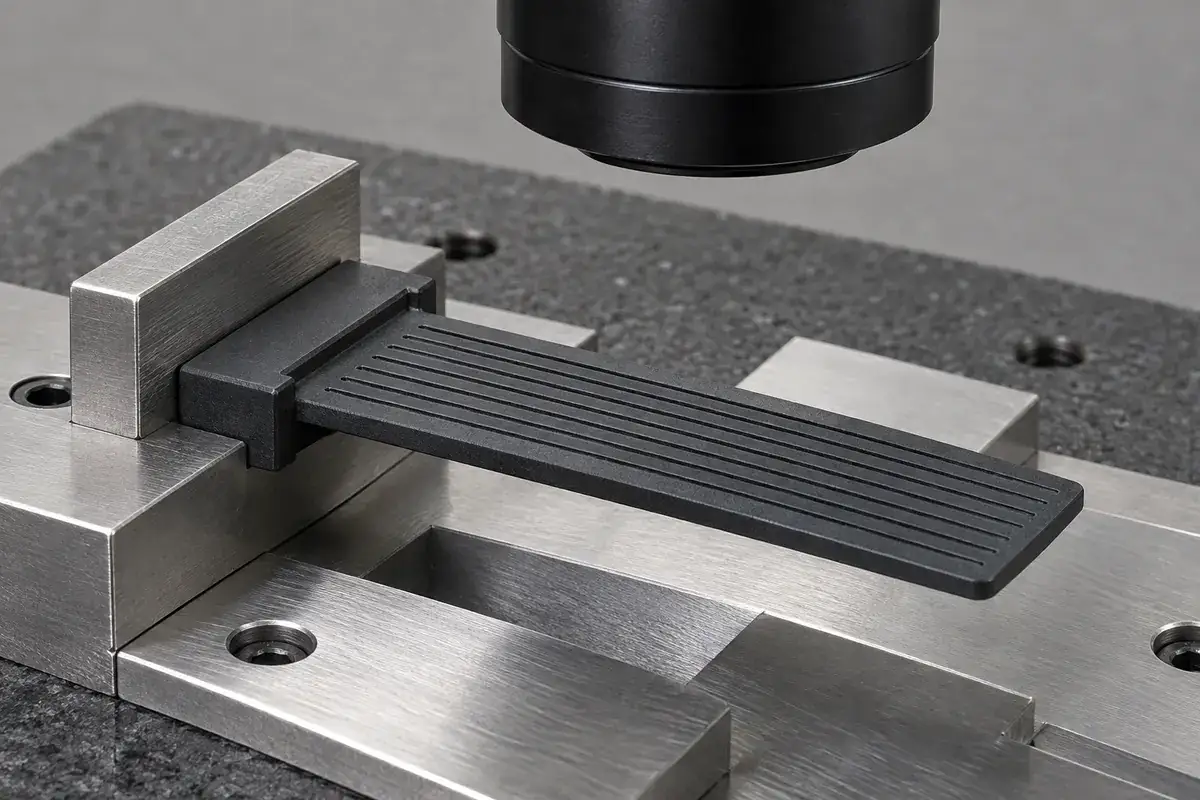
Connector Molding
Build a dimensional release plan for custom USB insulating tongues using functional datums, cavity identity, controlled sample states and separate assembly checks.
Read article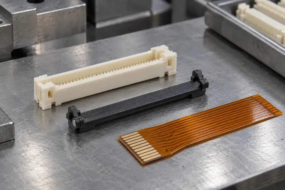
Connector Molding
Understand how FPC and FFC housings guide the cable while actuators control closure, and why their molded interfaces need separate acceptance criteria.
Read article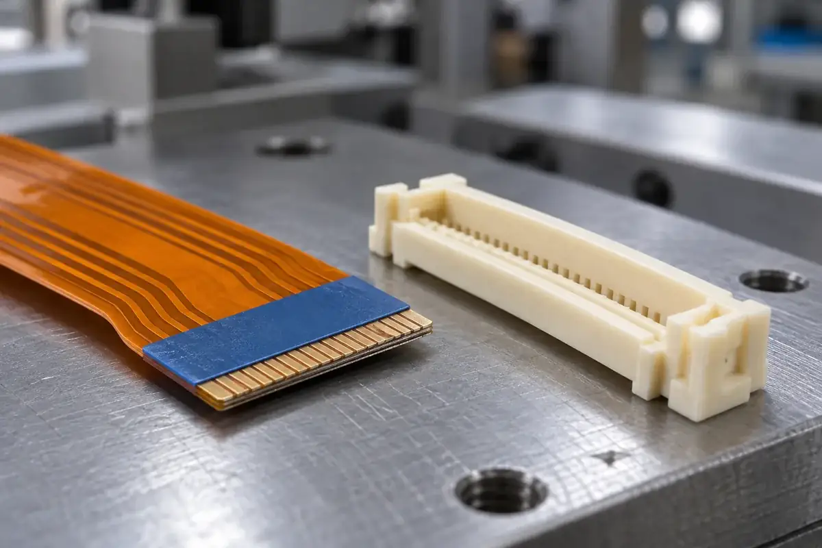
Connector Molding
Trace FPC cable thickness, stiffener position and housing clearance through insertion and closure without assuming a universal cable or slot dimension.
Read article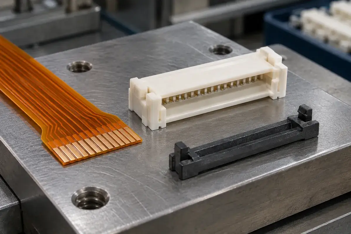
Connector Molding
Connect FPC pad orientation to housing references, cable routing and assembly checks, including why rotating a connector view can cause design mistakes.
Read article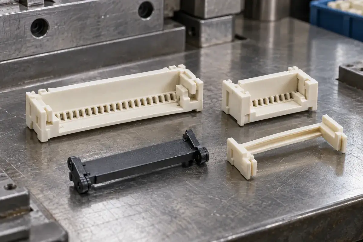
Connector Molding
Compare the motion, support and molding interfaces of flip-lock and slider FPC actuators, with practical trade-offs for access and assembly control.
Read article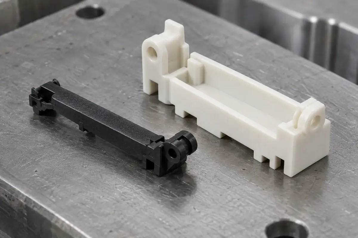
Connector Molding
Review pivot support, actuator overtravel and end-stop contact in molded FPC connectors, with a focus on load paths and meaningful inspection references.
Read article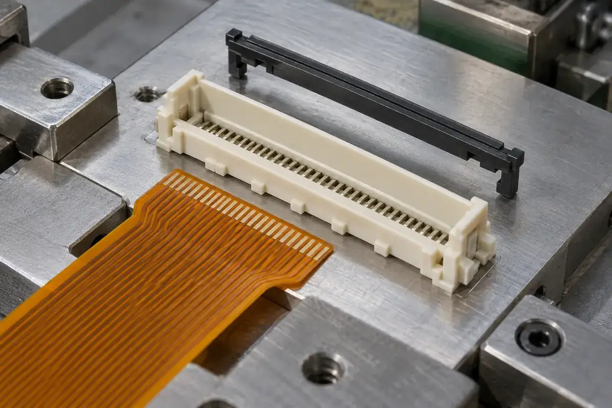
Connector Molding
Explain how cable leading edges, housing stops and contact regions define FPC insertion depth, and how to distinguish full seating from a misleading closure.
Read article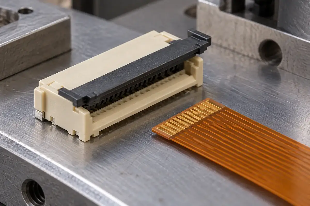
Connector Molding
Separate actuator travel, stop position and latch overlap in FPC connector parts, then diagnose skew, interference and incomplete engagement methodically.
Read article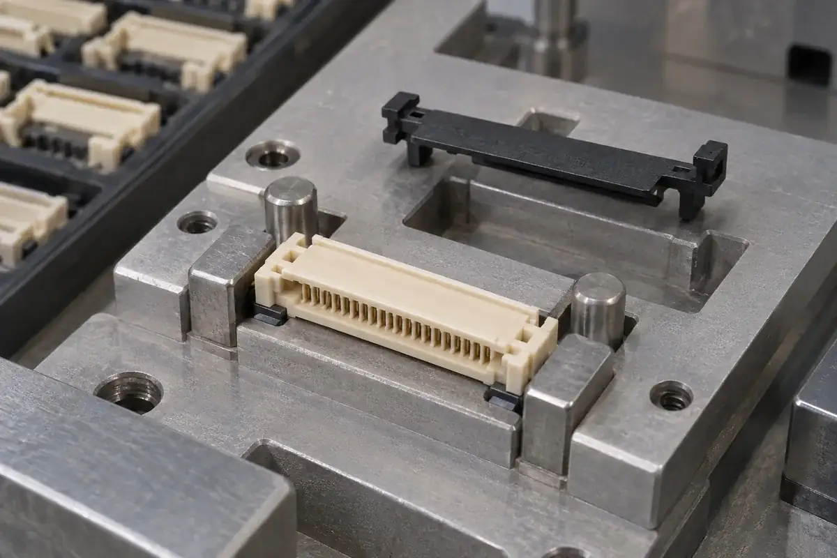
Connector Molding
Design FPC component assembly fixtures around functional datums, supported force paths and observable seating so tooling does not conceal part variation.
Read article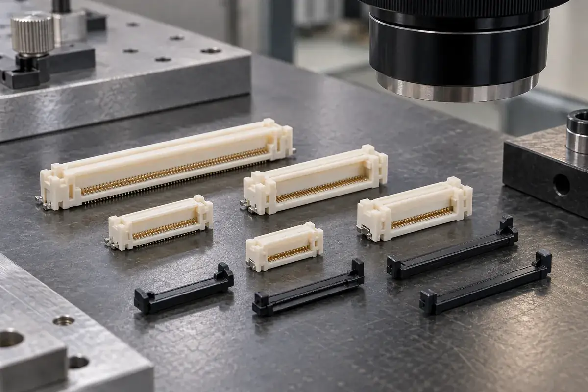
Connector Molding
Classify FPC housing and actuator marks by location and effect, then connect visual checks, dimensional inspection and assembly evidence without overclaiming.
Read article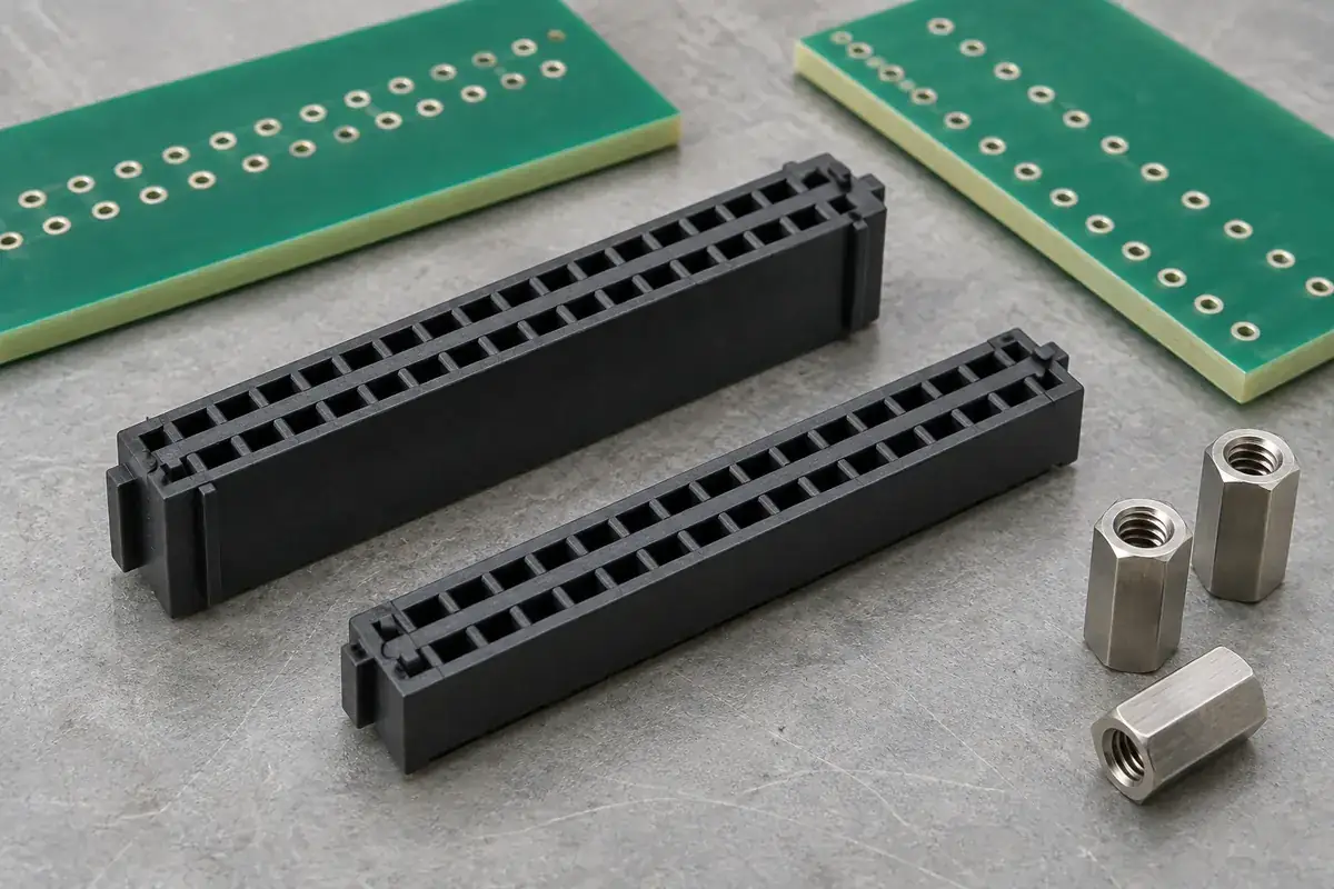
Connector Molding
Trace board spacing through housing seats, engagement depth and mechanical supports to define a stack height that works in the assembled product.
Read article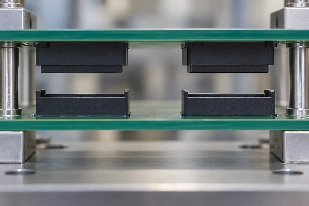
Connector Molding
Understand how guide geometry, board location and multiple connector pairs interact, then choose where alignment freedom belongs in a mezzanine assembly.
Read article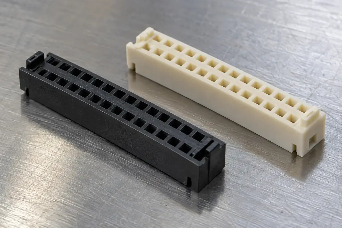
Connector Molding
Place polarization keys where they reject an incorrect orientation before sensitive features engage, while preserving guide strength and assembly access.
Read article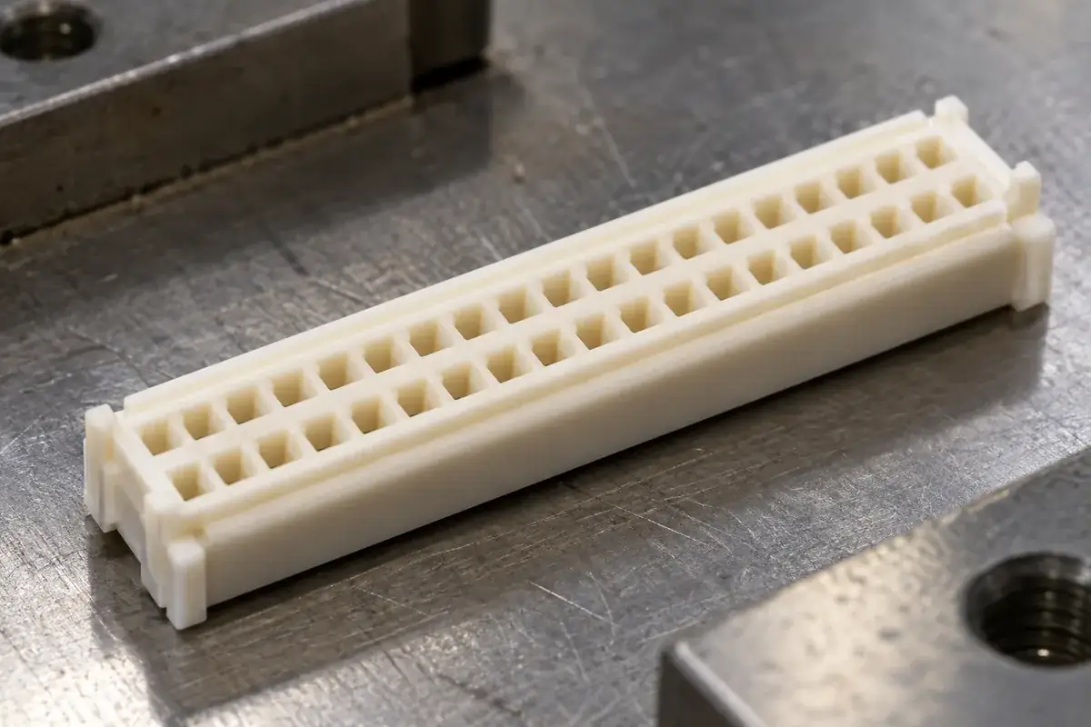
Connector Molding
Design connector housing lead-ins around capture, available movement and final guide engagement, balancing easier entry with wall strength and location.
Read article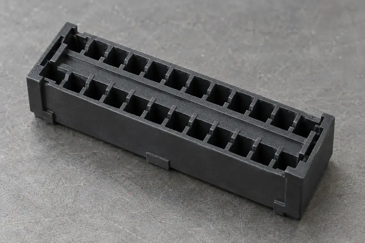
Connector Molding
Separate contact guidance, insertion travel and retention in molded board-to-board cavities, with clear load paths and assembly-specific acceptance.
Read article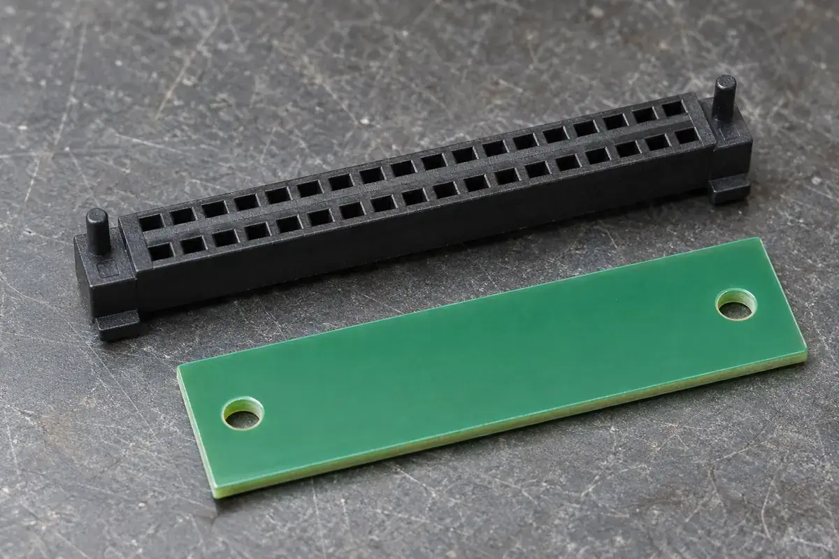
Connector Molding
Choose locating-peg fits from the board assembly sequence, separating placement guidance, seating and retention while avoiding conflicting references.
Read article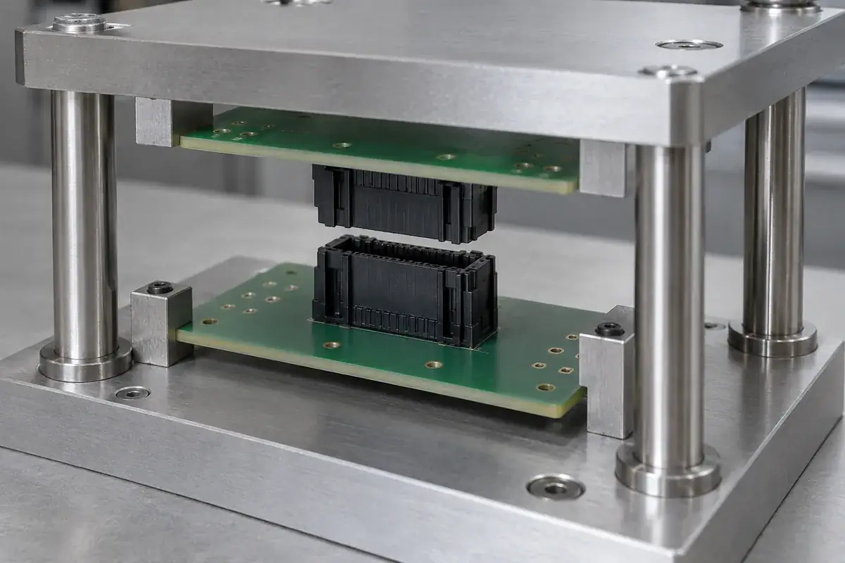
Connector Molding
Trace what stops a board-to-board assembly after engagement, and coordinate housing shoulders, supports and press travel to avoid unintended compression.
Read article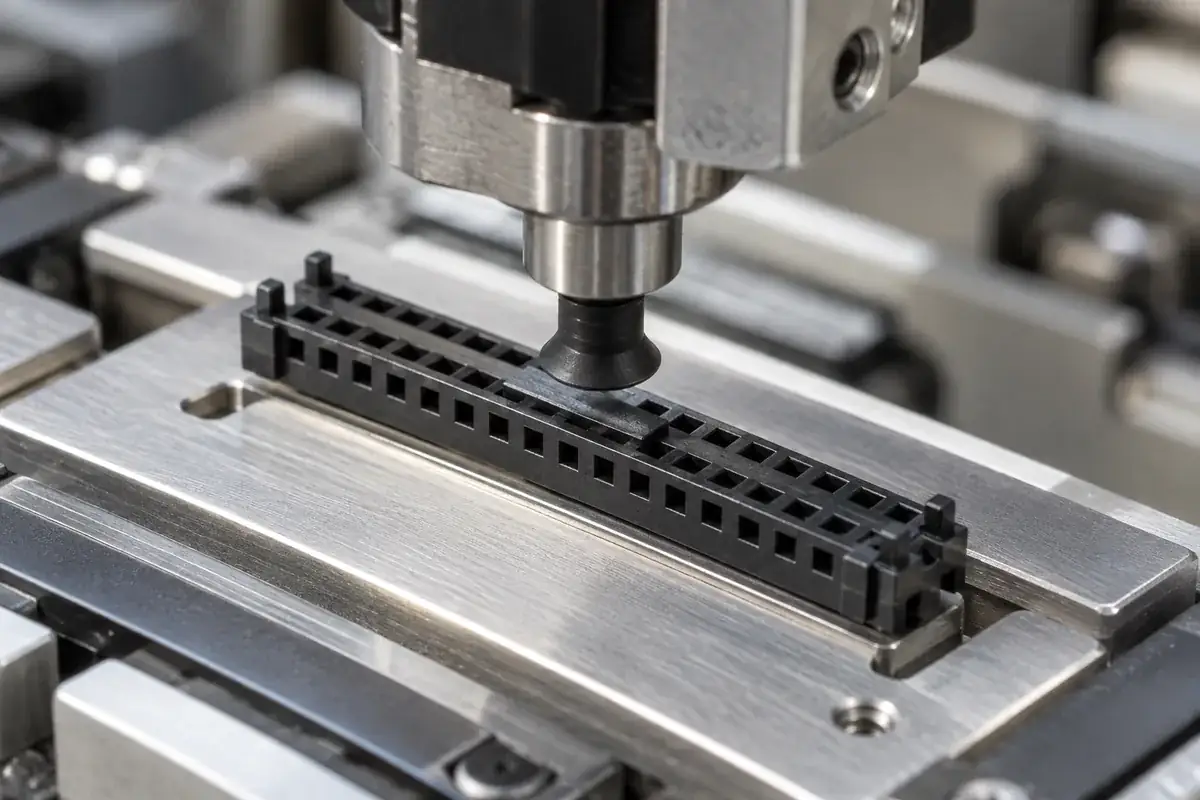
Connector Molding
Plan molded pickup pads and removable caps around nozzle access, stable handling and cavity clearance, then connect the design to packing and placement.
Read article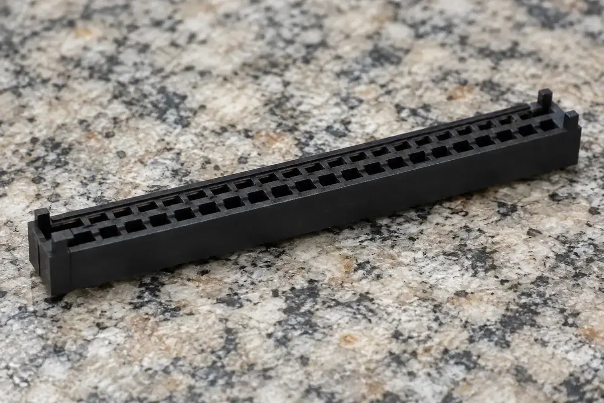
Connector Molding
Relate housing bow and twist to board seating, guide engagement and contact position, using defined free-state and assembled measurement conditions.
Read article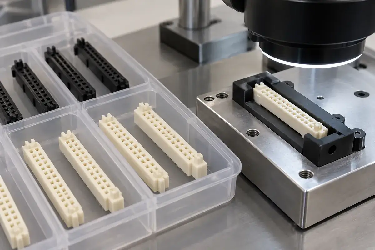
Connector Molding
Build a housing inspection plan that links mold-cavity identity to seating, guides and contact interfaces, with defined fixtures and meaningful fit evidence.
Read article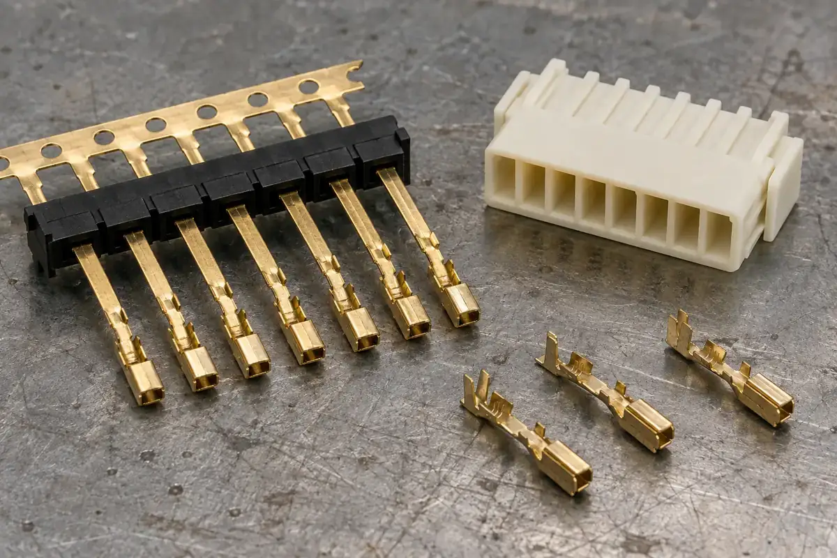
Connector Molding
Compare molding plastic around connector terminals with installing contacts afterward. Understand location, retention, tooling and assembly trade-offs.
Read article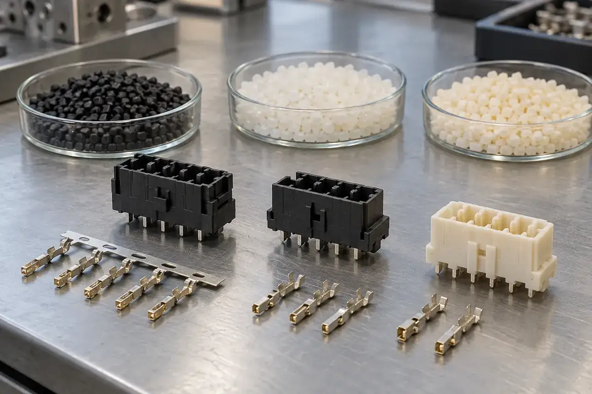
Connector Molding
Evaluate LCP, PBT and PA9T connector materials by exact grade, wall geometry, flow direction, moisture history and the intended assembly environment.
Read article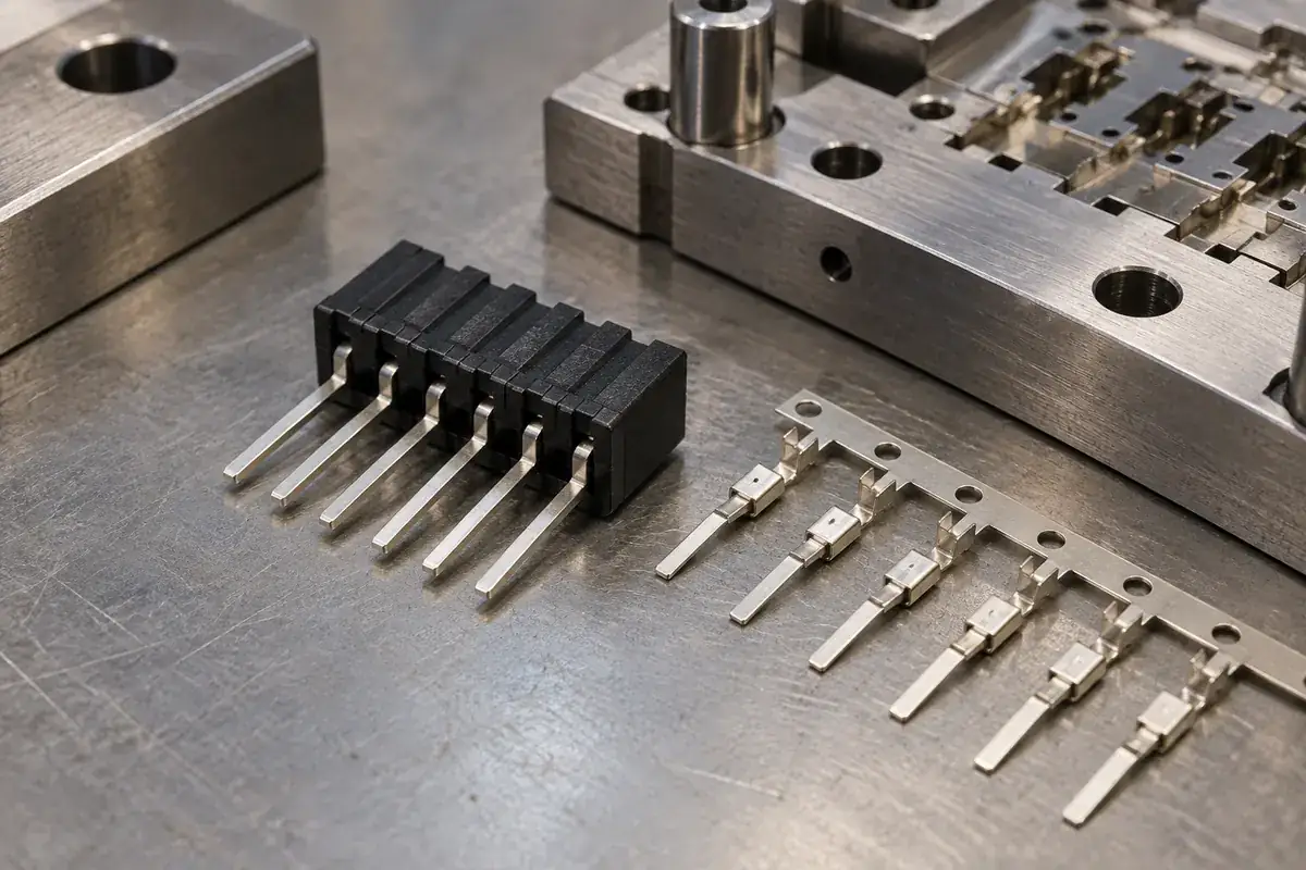
Connector Molding
Understand how melt loading, unsupported terminal spans and tool support affect connector terminal position, and how to isolate the cause of movement.
Read article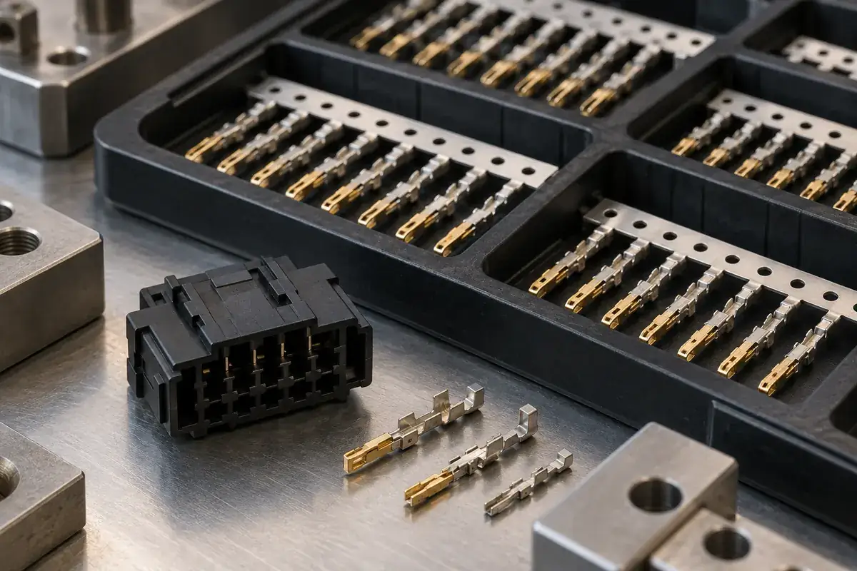
Connector Molding
Plan contact-zone protection, carrier handling and inspection so plated connector terminals survive loading, molding and transfer without avoidable damage.
Read article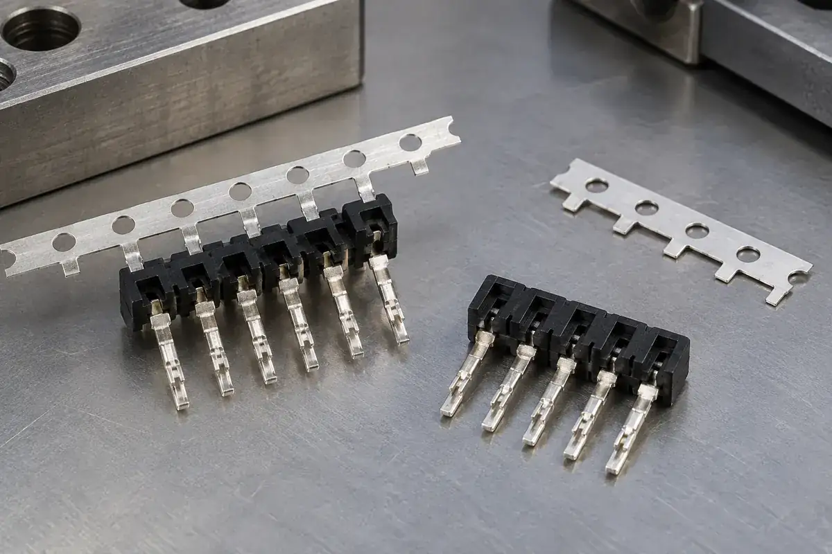
Connector Molding
Investigate connector movement after carrier cutoff by separating released restraint, trimming loads and measurement support from molding distortion.
Read article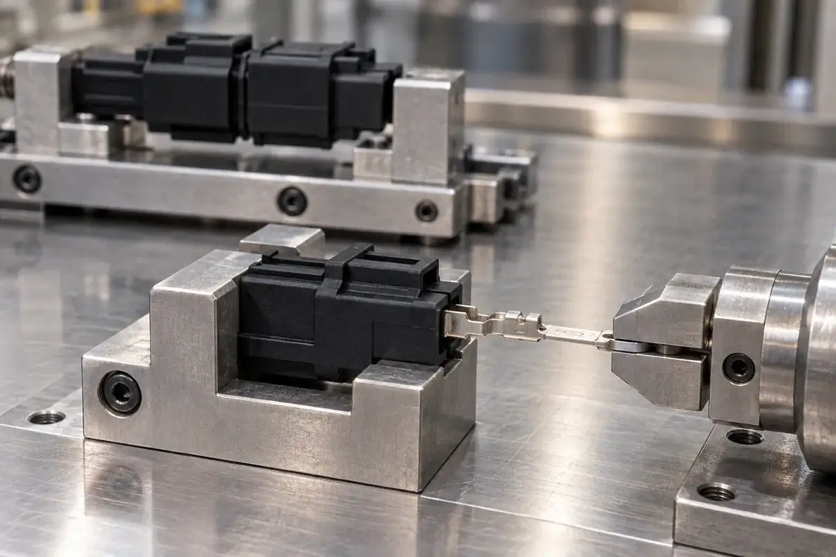
Connector Molding
Separate terminal retention from connector mating force with clear load paths, fixtures and acceptance conditions for insert-molded connector components.
Read article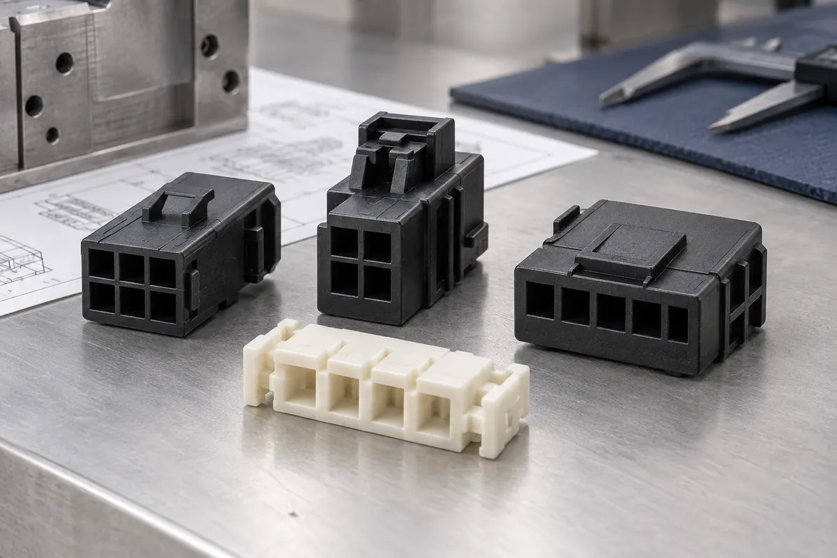
Connector Molding
Prepare a connector-insulator RFQ with mating geometry, resin, terminal assembly, inspection, traceability and clear production approval boundaries.
Read article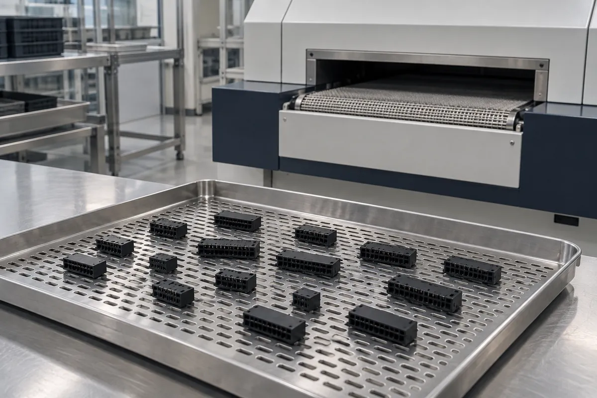
Connector Molding
Specify reflow exposure for molded connector parts using the actual thermal profile, resin grade, sample condition and post-process inspection requirements.
Read article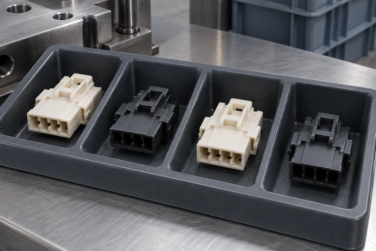
Connector Molding
Connect connector samples to mold cavity, material lot, production interval and inspection records without confusing a cavity mark with full traceability.
Read article
Connector Molding
Define responsibilities for connector bodies, contacts, seals and completed assemblies. Keep material recognition separate from finished-product approval.
Read articleShowing 109 of 109 articles
From design to production
Share your drawings, material requirements and production volume with our team.