
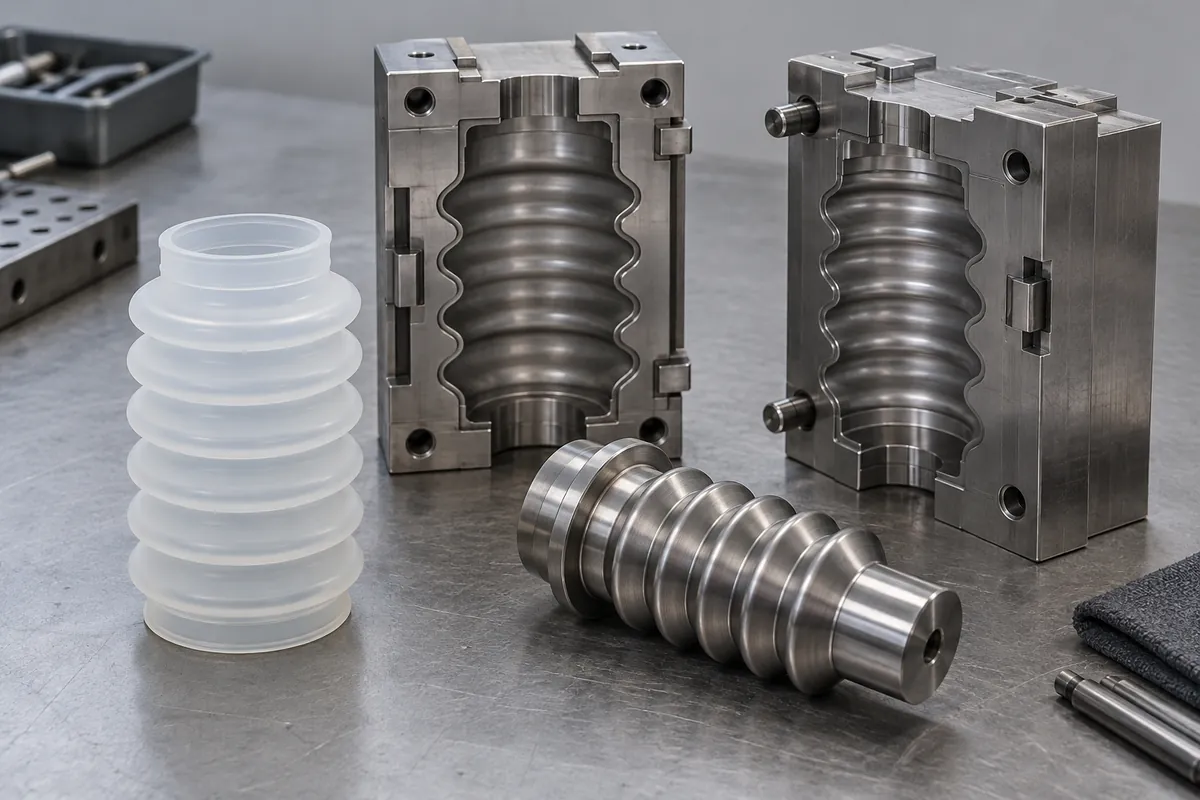
Product design illustrations. Final geometry, materials and acceptance criteria are project-specific.
Silicone flexibility can help release some undercut shapes, but it does not make every bellows profile straightforward to mold. Deep folds, narrow collars and changes in wall thickness can create difficult release conditions. Tooling feasibility should be reviewed alongside the working stroke, not after the component geometry is frozen.
Identify the intended molding route and compound first. LSR and other elastomer processes have different tooling and handling considerations. A supplier should explain how the proposed part will be formed and removed without relying on the general statement that rubber stretches.
Distinguish service strain from release strain
A bellows may experience a larger temporary deformation during demolding than during normal operation. A narrow opening may have to pass over a larger feature, or a fold may need to invert locally. Review that path explicitly rather than assuming the operating motion proves release feasibility.
Thin regions and sharp transitions can be vulnerable during removal. Increasing flexibility in the central folds does not necessarily protect a thick collar or a local notch. The tool review should identify where release loads act and how the part is supported while those loads are applied.
Manufacturer information such as WACKER's silicone resources supports material selection, but actual demolding capability depends on the compound, cure state, profile and tooling arrangement used for the part.
Choose parting and core strategies deliberately
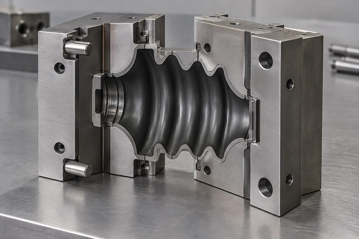
Review where mold sections meet and where the parting line will appear on the finished boot. Flash or mismatch at a sealing lip may be more important than the same feature on a noncritical outer fold. Mark the functional surfaces before selecting the most convenient split.
A core arrangement must accommodate the internal geometry and the release sequence. Depending on the profile, the supplier may propose a removable, segmented or otherwise specialized approach. Confirm the actual concept and its maintenance needs rather than assuming a simple straight-pull tool.
Consider how the part is supported as each tool element releases. An apparently feasible CAD separation may leave the flexible component hanging from one vulnerable feature. The process plan should include removal and handling, not only how the cavity closes around the nominal shape.
Account for finishing and cleanliness
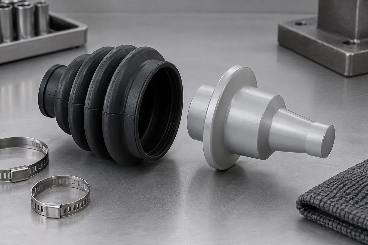
If trimming is required, define the permitted residual flash and the surfaces where trimming marks are unacceptable. A small feature may be cosmetic in one application and functional in another. Do not write a universal zero-flash statement without a measurable definition and an agreed method.
Review whether removal or finishing introduces particles or damage inside the folds. Inspection access can be limited in a deep convoluted part. Decide how development samples and production parts will be checked, especially where the boot protects a clean or sensitive mechanism.
Keep any release aid or post-treatment visible in the supply specification. A process substance may affect later bonding, cleanliness or fluid compatibility. It should not be introduced as an undocumented production convenience after the initial samples have been approved.
A quotation should identify replaceable tooling elements and the process for restoring worn functional edges where relevant. Bellows tools can contain repeated fine features, and maintenance may affect flash or local geometry. Agree which post-maintenance checks are required before returning the tool to production instead of relying only on the original sample approval.
Use trial molding to validate the manufacturing concept
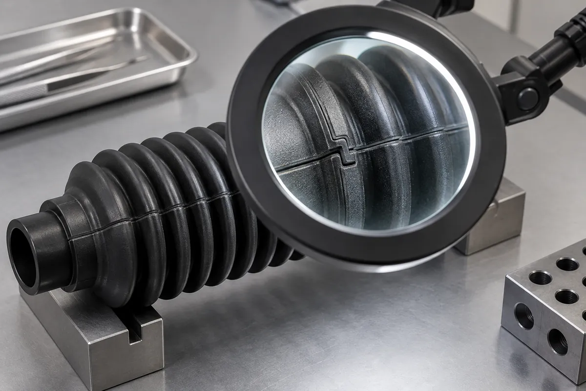
Evaluate more than one carefully selected specimen. Check whether release is repeatable across the relevant cavities and whether defects concentrate at a particular fold or collar. Record tool and process identity so later improvement can be distinguished from a change in inspection or sample selection.
Recheck usable stroke after any tooling-driven geometry change. A larger radius or altered fold depth may help production while changing compressed length, force or contact with the mechanism.
The approved design should therefore include a feasible release route and a validated functional envelope. If those cannot be reconciled, resolve the geometry or manufacturing approach explicitly instead of expecting material flexibility to absorb every conflict between tooling and operation.
Discuss the component and its acceptance requirements
Explore our custom silicone bellows & boots and the related project case study. Send the current drawing, mating-part details, operating conditions and required quantities. We can review tooling, molding and inspection as a defined supply scope, with development samples and production approval kept separate.