
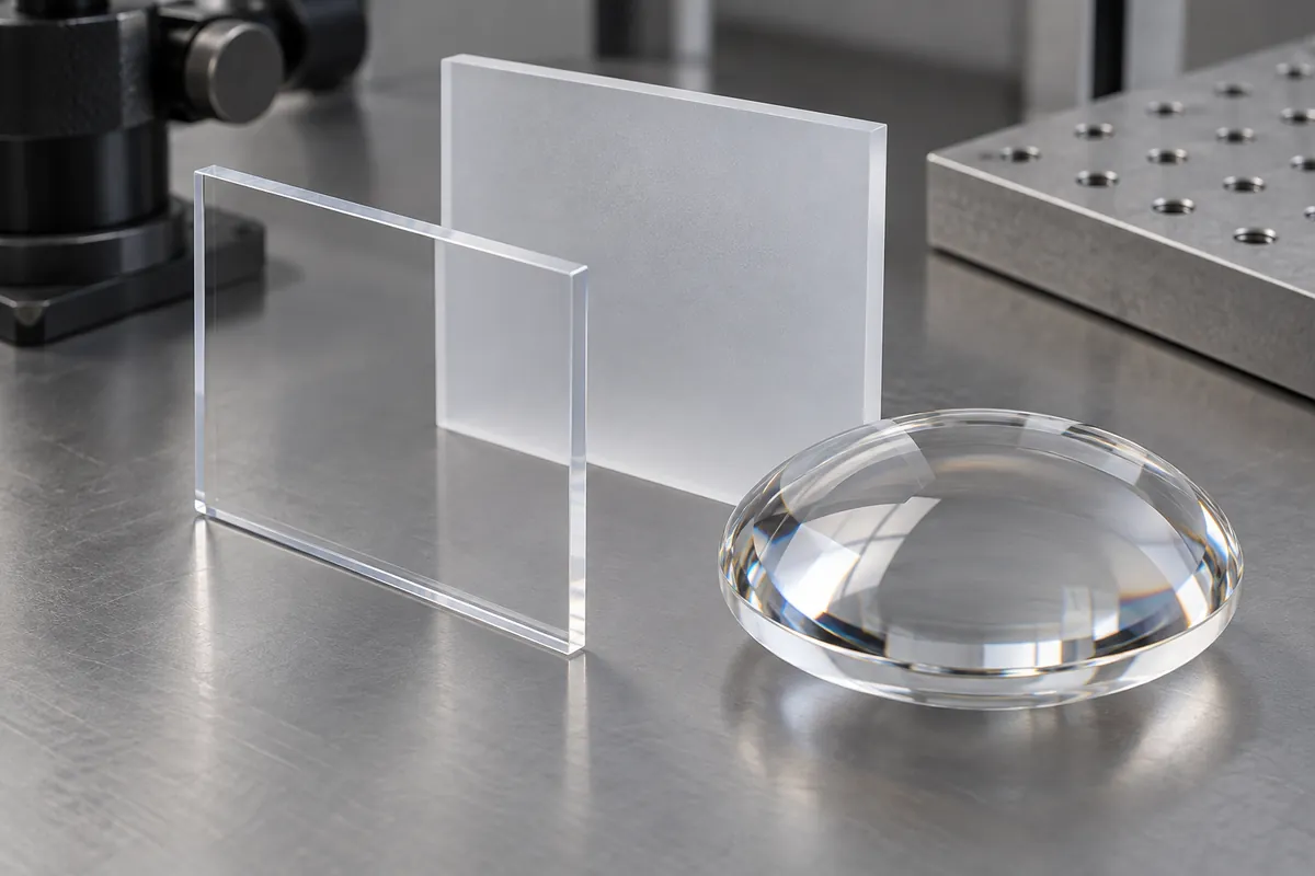
Product design illustrations. Final geometry, materials and acceptance criteria are project-specific.
A transparent part can transmit substantial light and still scatter enough of it to be unsuitable for a particular optical function. Haze and transmission describe different aspects of that behavior. Comparing two percentages without their measurement methods can produce a confident but incorrect material or supplier decision.
Begin with the purpose of the optic. A diffuser may intentionally redistribute light, while an imaging window may need to preserve a clear path. The acceptable balance between transmitted and scattered light depends on the application, so neither a high transmission value nor a low haze value is automatically sufficient.
Define what the instrument collects
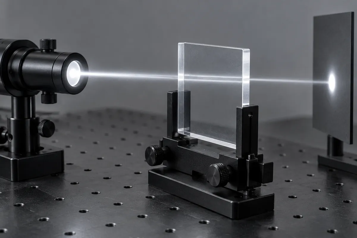
Transmission depends on the incident light and the portion collected after it passes through the specimen. Wavelength range, detector arrangement and whether scattered light is included affect the reported value. State the method rather than writing a percentage that appears independent of the test setup.
Haze describes scattering under a defined measurement convention, not simply how cloudy a part looks in a photograph. Visual inspection may identify an obvious problem, but it cannot replace the specified instrument method when the acceptance requirement is numerical.
Gigahertz-Optik's light-measurement reference explains why measurement geometry matters. Use a relevant method for the actual specimen rather than assuming all optical instruments measure the same quantity.
Keep specimen geometry visible
A flat plaque and a curved lens do not necessarily direct transmitted light toward the detector in the same way. A lens can redirect light outside the collection region even when the material itself is unchanged. Compare equivalent specimens or explain how the method accounts for their different shapes.
Thickness and surface condition also belong in the comparison. A material datasheet may report a value for a specified plaque thickness, while the component has changing optical path length. Do not present the datasheet value as a guaranteed measurement of every region of the finished lens.
Identify the clear aperture and the area being evaluated. Gate-adjacent material, mounting rims or intentionally textured areas may not belong to the optical working zone. A whole-part average can conceal a local defect in the region that actually controls system performance.
Separate defects from intended function
Surface texture, internal inclusions, bubbles and contamination can affect light differently. Record the observed feature and location rather than describing every unfavorable result as low transparency. That distinction helps determine whether the next action belongs to material handling, molding, finishing or cleaning.
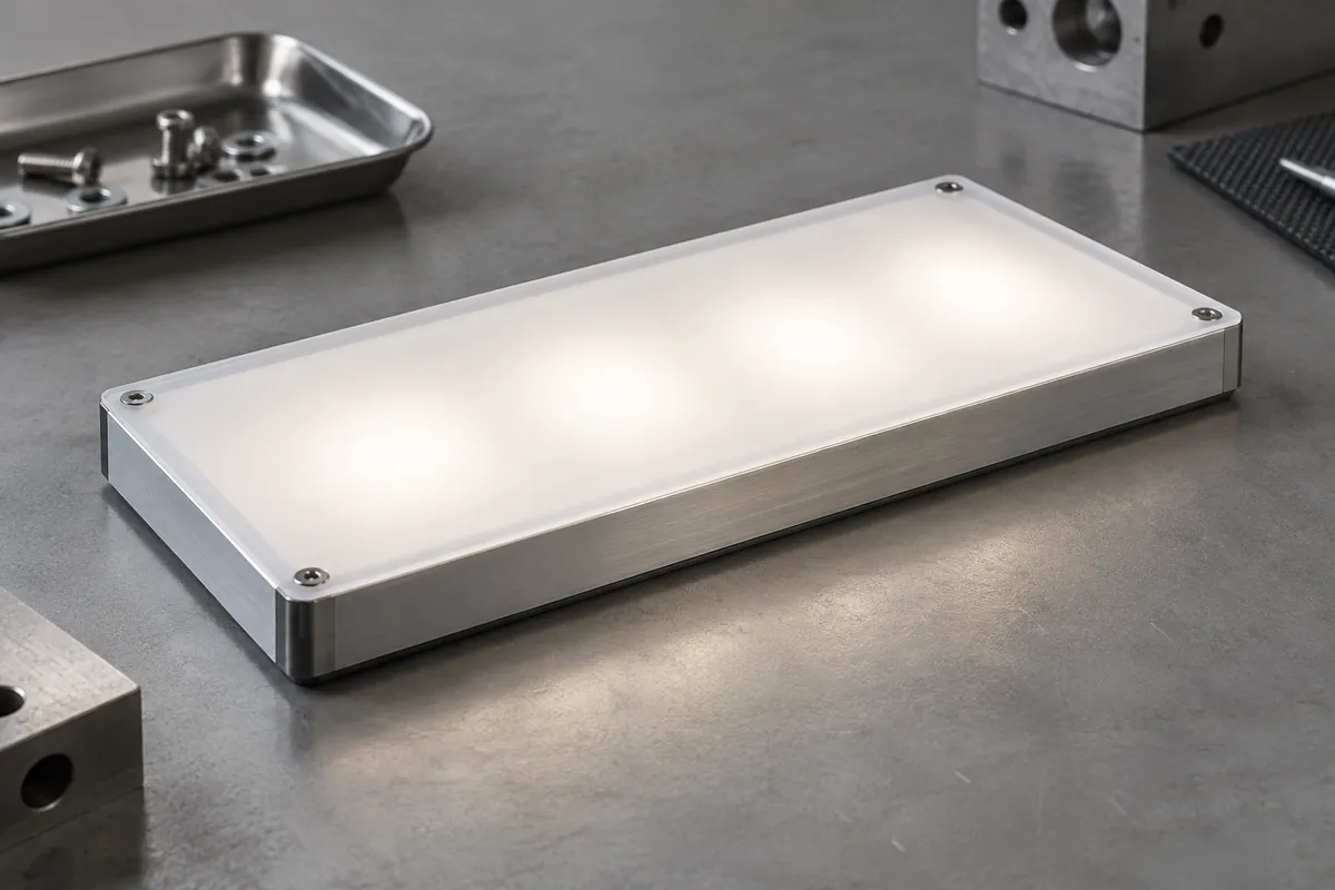
A deliberately diffusing surface should be evaluated against its intended distribution, not rejected simply because it is hazy. Conversely, a polished-looking surface may still fail an optical requirement. The drawing should state the functional expectation for each zone instead of treating the entire part as uniformly clear.
Check the specimen after relevant exposure where aging or cleaning matters. Record conditioning and measurement timing so a change can be interpreted. A before-and-after comparison is meaningful only if the test geometry and specimen state remain controlled.
Agree whether results are reported spectrally or as a weighted summary. A single percentage may hide variation across the wavelength range important to the application. Retaining the underlying measurement conditions helps the optical team decide whether a supplier comparison is meaningful rather than treating every transmission figure as the same characteristic.
Connect component measurements to the assembled system
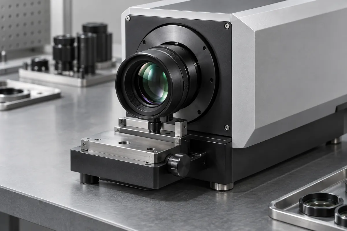
For lighting assemblies, total luminous flux and beam distribution are separate outcomes. An integrating-sphere measurement can support a flux evaluation, but it does not by itself map the spatial uniformity of the projected beam. Choose the instrument and method for the claim being made.
Review the complete inspection plan with the source, mounting and alignment conditions defined. A lens supplier's material test and the customer's assembled optical test can both be useful without being interchangeable.
The acceptance report should name the quantity, method, sample count and specimen configuration. This makes comparisons reproducible and prevents a favorable material percentage from becoming an unsupported claim about focal quality, beam uniformity or finished-product efficiency.
Discuss the component and its acceptance requirements
Explore our custom plastic optics and the related project case study. Send the current drawing, mating-part details, operating conditions and required quantities. We can review tooling, molding and inspection as a defined supply scope, with development samples and production approval kept separate.