
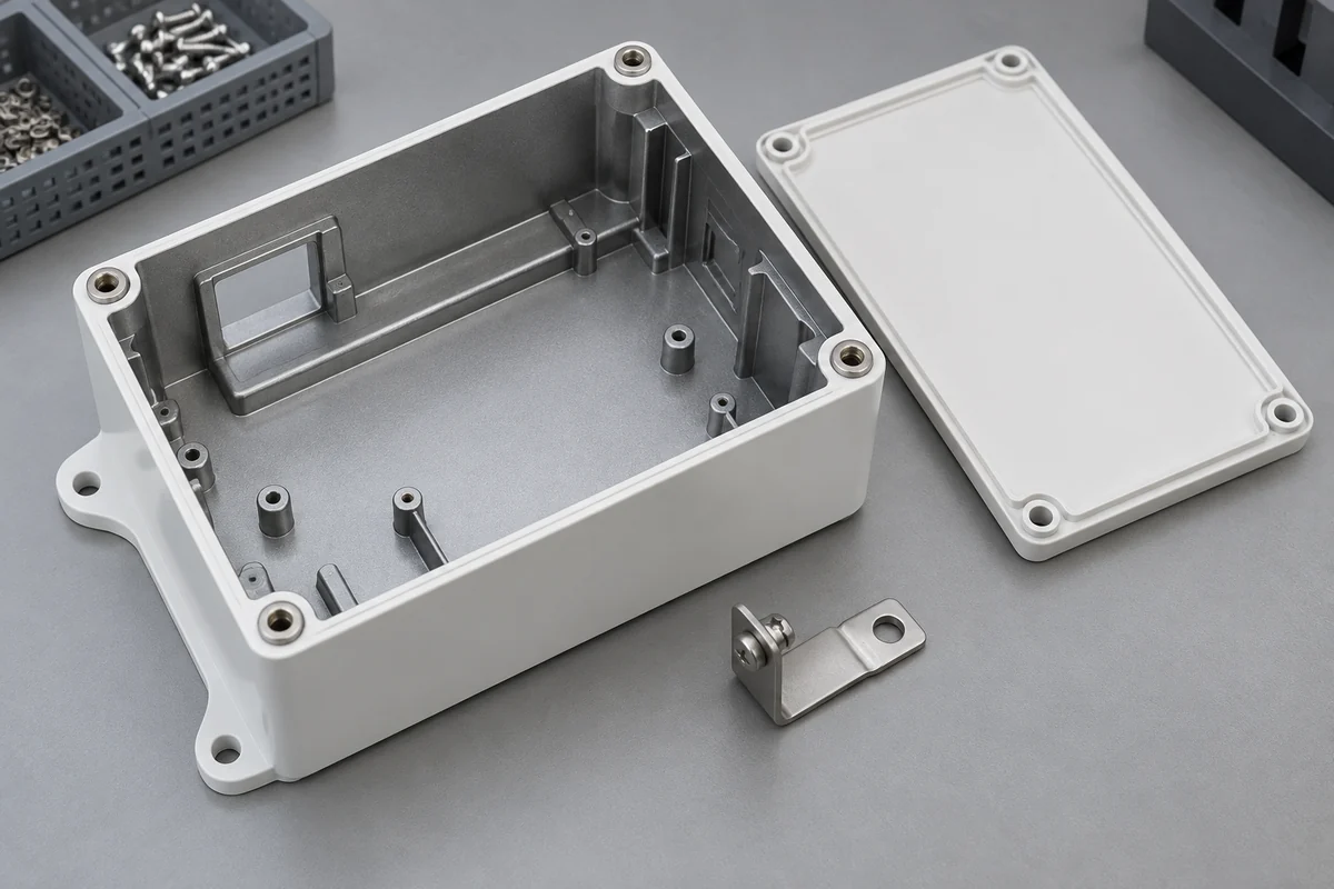
Product design illustrations. Final geometry, materials and acceptance criteria are project-specific.
Adding conductive paint to the inside of a plastic medical-equipment housing creates a new manufacturing interface. The result depends on the molded substrate, surface preparation, coating and the way the enclosure connects after assembly. Treating the paint as a final cosmetic step can leave critical decisions unresolved until the first coated parts arrive.
The scope in this guide is the plastic component and its coating. Electromagnetic compatibility belongs to the complete equipment configuration and its applicable evaluation. A useful coating report can support that work, but it cannot by itself establish that an instrument passes emissions or immunity requirements.
Separate material properties from system performance
A coating supplier may report sheet resistance and shielding effectiveness under specific test conditions. Those figures do not describe every molded enclosure made with that coating. Parker Chomerics' conductive coating range, for example, distinguishes formulations and published performance characteristics. The project still needs to choose the relevant system and verify its application.
Do not convert a resistance value into an equipment-level shielding claim. Apertures, seams, grounding interfaces and installed cables can change the behavior of the complete enclosure. Ask the device designer to define the required shield boundary and contact scheme before the coating quotation is finalized.
Control the substrate that reaches the coating process
Document the exact resin purchase specification, color formulation and molded-part history. Release agents, residues, handling and storage may affect preparation requirements. If a supplier proposes a material change to improve coating behavior, obtain the relevant declaration rather than inferring additive content from a color or grade suffix alone.
Cleaning or plasma treatment should be specified as a controlled process step with its own parameters and handling requirements. It is not a universal cure for any adhesion problem. Agree the sequence between preparation, storage, coating and cure, and evaluate the actual resin and coating combination used for the proposed part.
Draw masking and contact lands explicitly
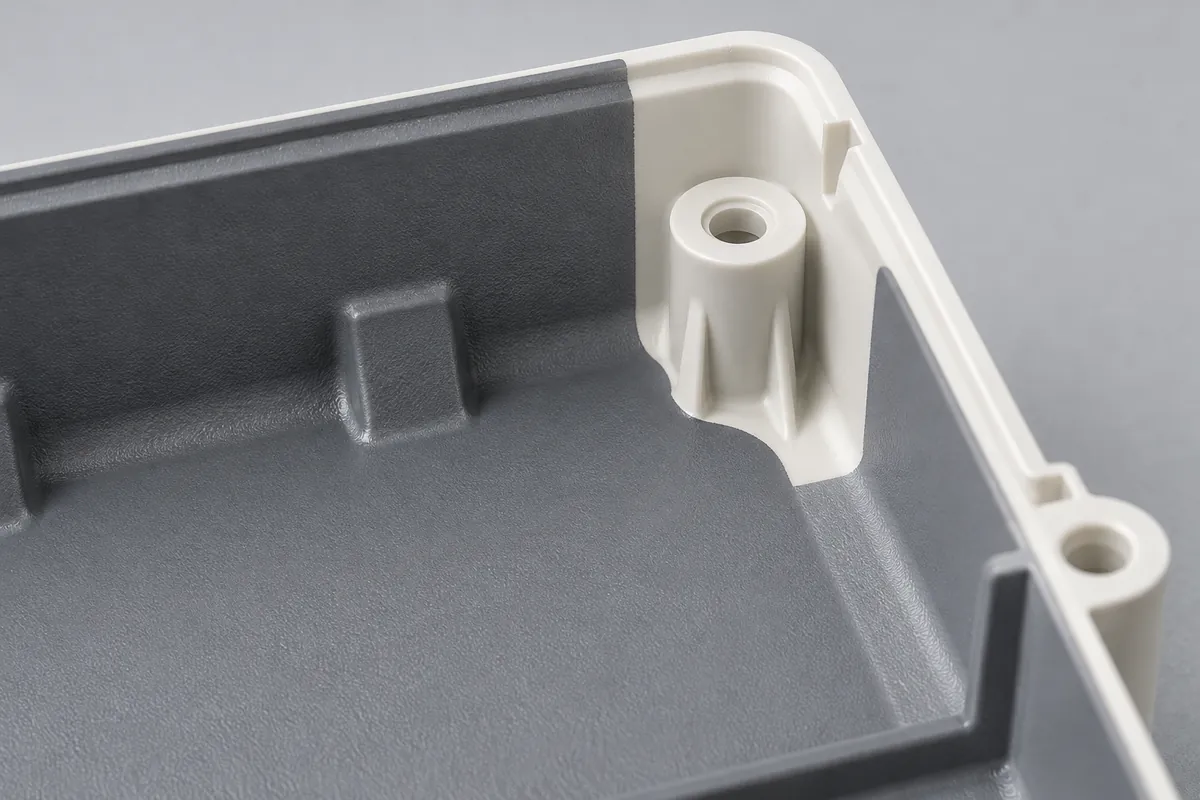
Identify screw threads, display seats, adhesive lands and other keep-out areas. Coating on the wrong surface can alter fit or contaminate an interface, while a missing coating area can interrupt the intended conductive path. A general note to coat the inside does not resolve these competing needs.
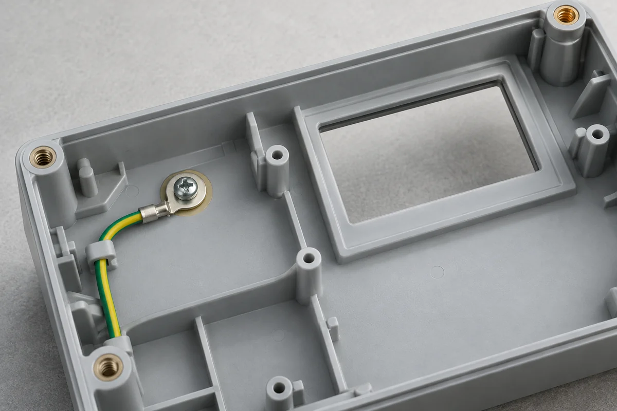
The drawing should distinguish an area requiring coating from an area intended to make electrical contact. A fastener touching a painted wall is not automatically a reliable grounding scheme. The contact design, assembly method and any gasket should be reviewed by the team responsible for the equipment's electrical architecture.
Include access for the coating operation and inspection. Deep recesses, narrow returns and masked corners may be difficult to cover or measure consistently. Discuss those features before tooling so that a local geometry change can be evaluated while there is still a practical opportunity to make it.
Use separate checks for separate failure modes
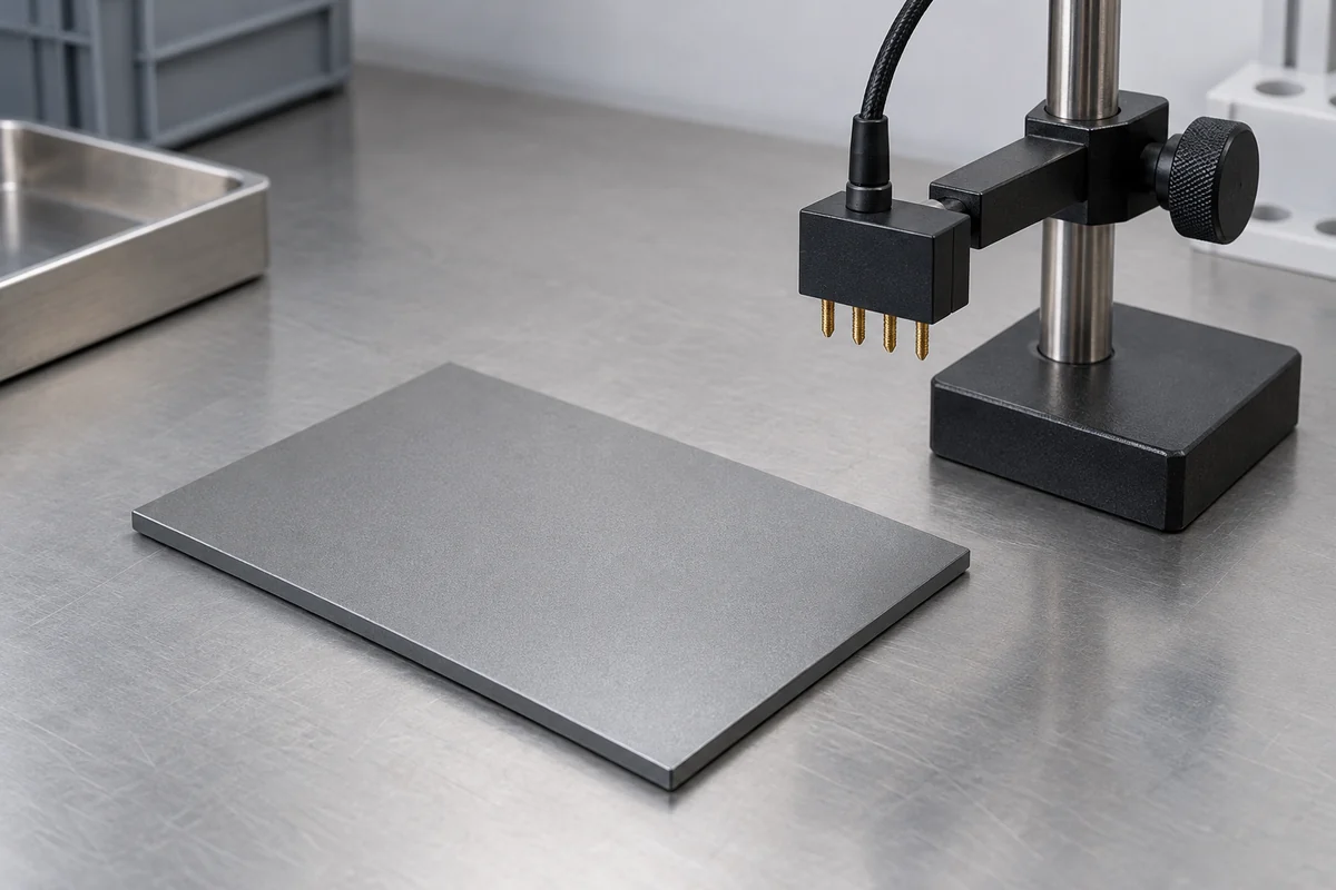
Appearance, coverage, thickness, adhesion and resistance answer different questions. A coating can look continuous while its contact performance is unsuitable; a low resistance reading does not demonstrate acceptable adhesion after exposure. Select the relevant checks and define locations, specimen state, sampling and acceptance with the coating and equipment teams.
Use the specified measurement method consistently and keep readings linked to sample identity. A report should not mix results from an unassembled flat coupon with housing measurements without saying so. If the instrument or probe geometry changes, review whether the new measurements remain comparable to the approved method.
Similarly, agree any environmental conditioning rather than claiming lifetime durability from an initial inspection. The housing exposure guide explains why cleaners, stress and the final material combination need a defined evaluation. Internally coated areas may have different exposure conditions from the wiped external face.
Keep coating approval attached to a configuration
Record the molded-part revision, resin specification, surface preparation, coating system, cure and masking plan used for the accepted specimens. If several variables were changed between trials, the result may support the combined change without proving which single variable caused the improvement.
Keep the component release and device-level review separately signed off. Our analyzer housing case study reports component inspection values without turning them into an EMC certificate. The same boundary belongs in a purchasing specification: define the evidence that the enclosure supplier must deliver, and identify who completes the equipment evaluation.
Discuss your custom enclosure
Explore our custom injection-molded medical device enclosures and the tabletop analyzer housing project. Share the controlled drawing, intended use, quantities and acceptance requirements. Component supply and finished-device qualification should have clearly assigned responsibilities.