
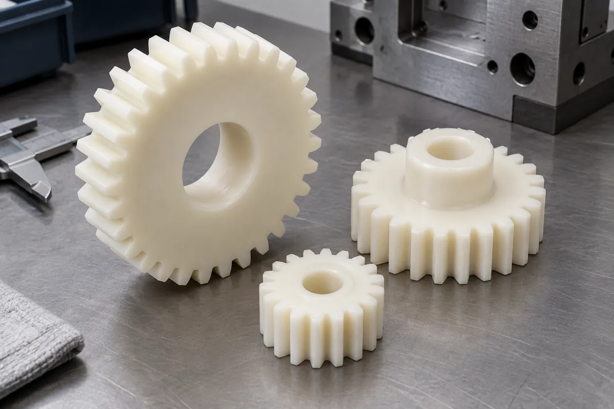
A photograph of a worn gear is useful for starting a conversation, but it is not enough to quote a production replacement responsibly. It does not establish the original tooth definition, the mating gear, the working center distance or the load history. Copying the visible outline can reproduce wear or an earlier design compromise instead of the intended geometry.
A custom injection-molded gear RFQ should describe a working gear pair and a supply program, not just one toothed wheel. This guide focuses on molded polymer parts made to an agreed design. It is not a stock replacement-gear catalog, and it does not assign a load rating to a part from its appearance.
Product design illustrations. Final geometry, materials and acceptance criteria are project-specific.
Define the teeth without relying on the photograph
Provide the gear drawing and 3D model, including the tooth system and the parameters your designer uses to define it. For a spur gear, that commonly includes tooth count, module or diametral pitch, pressure angle, face width and any profile modification. State the units and controlling revision. Do not assume that an outside diameter uniquely identifies the correct tooth geometry.
Describe the mating gear as well. A drawing, controlled supplier specification or identified sample can help, but mark any reverse-engineered information as provisional until it is verified. If the existing part is damaged, distinguish measured remaining geometry from the design values that still need reconstruction.
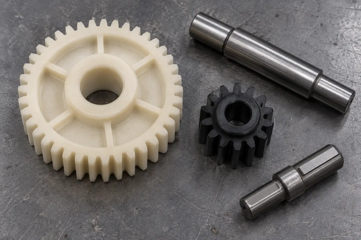
Describe how the gear is loaded
Provide the expected speed, torque or load history, direction changes, starts and stops, and any abnormal event that the design must address. Distinguish normal operation from a stall or overload condition. An annual operating-hours estimate is not a substitute for the duty cycle within those hours.
Add the environment: temperature range, moisture exposure, contaminants, lubrication and any restrictions on lubricant use. Identify whether a noise requirement applies to the open gear pair or to the complete assembled product. This prevents a component supplier from being asked to guarantee a system-level result without the surrounding design.
Delrin's gear-material overview identifies friction, wear and stiffness as relevant material properties. Use such guidance to screen exact grades, not to infer an allowable torque for an untested gear. A grade recommendation and a working-drive design calculation remain separate engineering tasks.
Include the hub, bore and supports
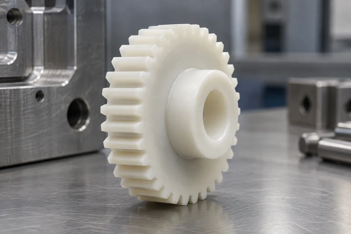
The teeth do not work independently of the mounting. State how the gear is located on the shaft, how axial movement is controlled and which surfaces establish the inspection datum. A round bore, D-bore, molded insert and interference-fit hub create different review questions. If an insert is supplied by the customer, include its drawing and incoming inspection requirements.
Supply the assembly's nominal center distance and its permitted variation. Housing, bearing and shaft features can influence the gear mesh. The backlash and center-distance guide explains why a nominally correct pair still needs its support arrangement reviewed.
| Area | Input to provide | Decision to close |
|---|---|---|
| Tooth geometry | Controlled tooth definition, model and mating gear. | Missing parameters or provisional reverse-engineered features. |
| Operation | Duty, speed, load, environment and lubrication. | Component screening versus drive-system validation. |
| Mounting | Shaft, bore, axial location, support and center distance. | Assembly tolerance relationships and inspection datums. |
| Supply | Trial quantity, first order, repeat forecast and reports. | Tooling approach, approval stages and commercial scope. |
Ask what will actually be inspected
Specify which tooth and mounting characteristics require measured values and which combined functional checks are expected. A visual check of tooth count is not a tooth-accuracy report. If a particular grade or standard is required, give its designation and edition and agree how compliance will be demonstrated.
Keep inspection and endurance testing separate in the quotation. A dimensional report can support drawing approval without establishing wear life or acoustic performance. The gear inspection guide covers the acceptance package, while the wear and noise guide addresses operating evaluation.
Compare tooling and production at the same boundary
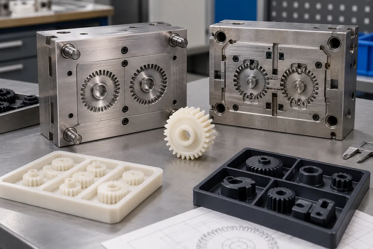
Ask the supplier to identify the proposed cavity arrangement, trial deliverables, anticipated development steps and any secondary operations. Do not assume that every feature will be molded to final acceptance without discussion. If a bore needs additional work, preserve that as an explicit scope item rather than hiding it inside a nominal part price.
Separate initial samples, the first firm order and uncommitted repeat demand. Injection molding involves a tool investment, so the economics depend on the actual program and design stability. No universal order threshold determines whether molding is the right choice. A prototype or a stock part may answer an early fit question without becoming the final production route.
Before releasing tooling, close a short assumptions list covering geometry, material, inspection, operating validation and change approval. The most useful RFQ is not the longest one: it is the one from which both parties can identify exactly what they are agreeing to make and how acceptance will be decided.
Turn the review into a defined molding scope
Explore our custom injection-molded plastic gears and the related illustrative engineering study. Send the drawing revision, counterpart details, intended use and the decisions still open. Development samples and production approval should have separate, agreed deliverables.