
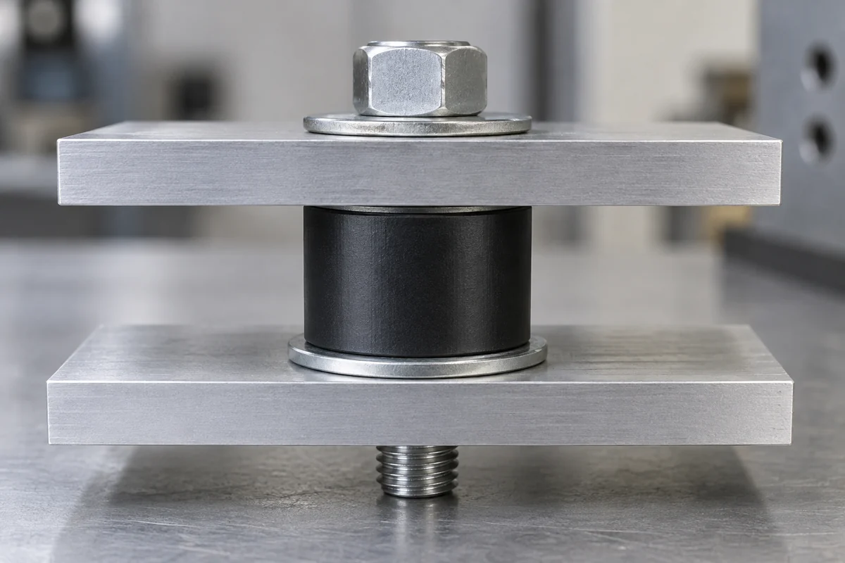
Product design illustrations. Final geometry, materials and acceptance criteria are project-specific.
A freshly tightened joint can feel secure while leaving an important question unanswered: will the plastic spacer maintain the required support over time? An assembly check confirms that the screw engages and the parts fit today. It does not establish the remaining clamp load, support height or alignment after a long period under compression.
For that reason, define the function that must be preserved before selecting a test. A spacer may locate a board, maintain a service gap, resist vibration-induced movement or support a sealing arrangement. These outcomes need different observations. A universal instruction to torque the bolt and inspect the part is too vague to distinguish success from a hidden loss of function.
Separate creep from stress relaxation
The Delrin design guide distinguishes increasing deformation under sustained stress from decreasing stress at a maintained strain. These related behaviors help frame a bolted polymer joint, but its actual response depends on the complete assembly stiffness and boundary conditions. A real joint should not automatically be treated as a perfect constant-load or constant-displacement experiment.
Use exact-grade information to screen the material, including the relevant temperature and time conditions. A tensile strength value from a short test does not establish a long-term compression limit. Likewise, a curve for one acetal or reinforced nylon formulation is not evidence for another grade simply because both parts look similar.
The useful engineering question is how much movement or preload change the application can tolerate. Put that limit beside the intended service conditions. Without a functional limit, a test can produce a set of measurements but still leave the team unable to decide whether the design should be accepted.
Follow the bearing contact rather than the outline
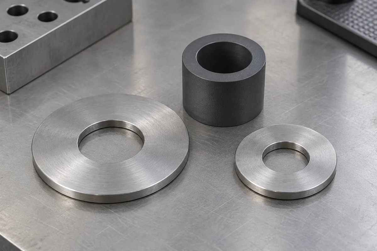
A broad outside diameter does not ensure that the entire face carries load. The washer, counterbore, edge radius or a tilted counterpart may reduce the contact to a smaller region. Review the actual mating surfaces and the likely contact pattern. A local contact problem can be missed if the analysis simply divides bolt force by the full circular outline.
A larger washer is one option to evaluate, not an automatic cure. It must fit the available space, remain adequately supported and avoid bending against an irregular face. Its interaction with the board or panel matters too. Changing the washer may shift the problem into a different component unless the complete load path is reviewed.
Do not equate installation torque with retained preload
Torque is an installation control whose relationship with bolt tension depends on the fastener and friction conditions. A specified torque therefore needs its own assembly basis. It is not a direct record of the clamp force remaining after temperature exposure or a loaded dwell, and a second torque reading is not automatically an equivalent preload measurement.
Specify the screw, washer, engagement, tightening sequence and lubrication state used in the evaluation. Keep those details with the sample record. If the production line later changes a fastener coating or a washer supplier, determine whether the original evaluation still represents the delivered assembly.
A through-bolt, a screw engaging molded polymer threads and a screw engaging a metal insert impose different local demands. Our threaded standoff comparison explains those configurations. Establish the intended design before borrowing an installation limit from another type of support.
Plan a test around the actual operating sequence
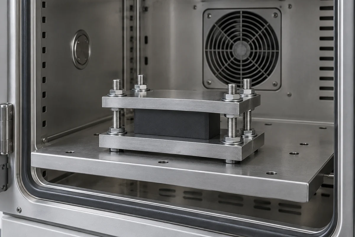
Consider assembly, storage, start-up, hot operation, cool-down and maintenance rather than testing only at a convenient room condition. Choose the combinations that represent the application and define how the assembly will be observed. Record height or displacement, retained load where measured, fit and any visible damage as separate findings.
A short, severe test does not prove an arbitrary number of service years without a justified acceleration model. It can still reveal a design weakness or compare candidates under the stated conditions. Report it at that level: identify the configuration, duration, exposure, sample count and result, and do not convert it into an unsupported lifetime claim.
Choose a corrective action that addresses the load path
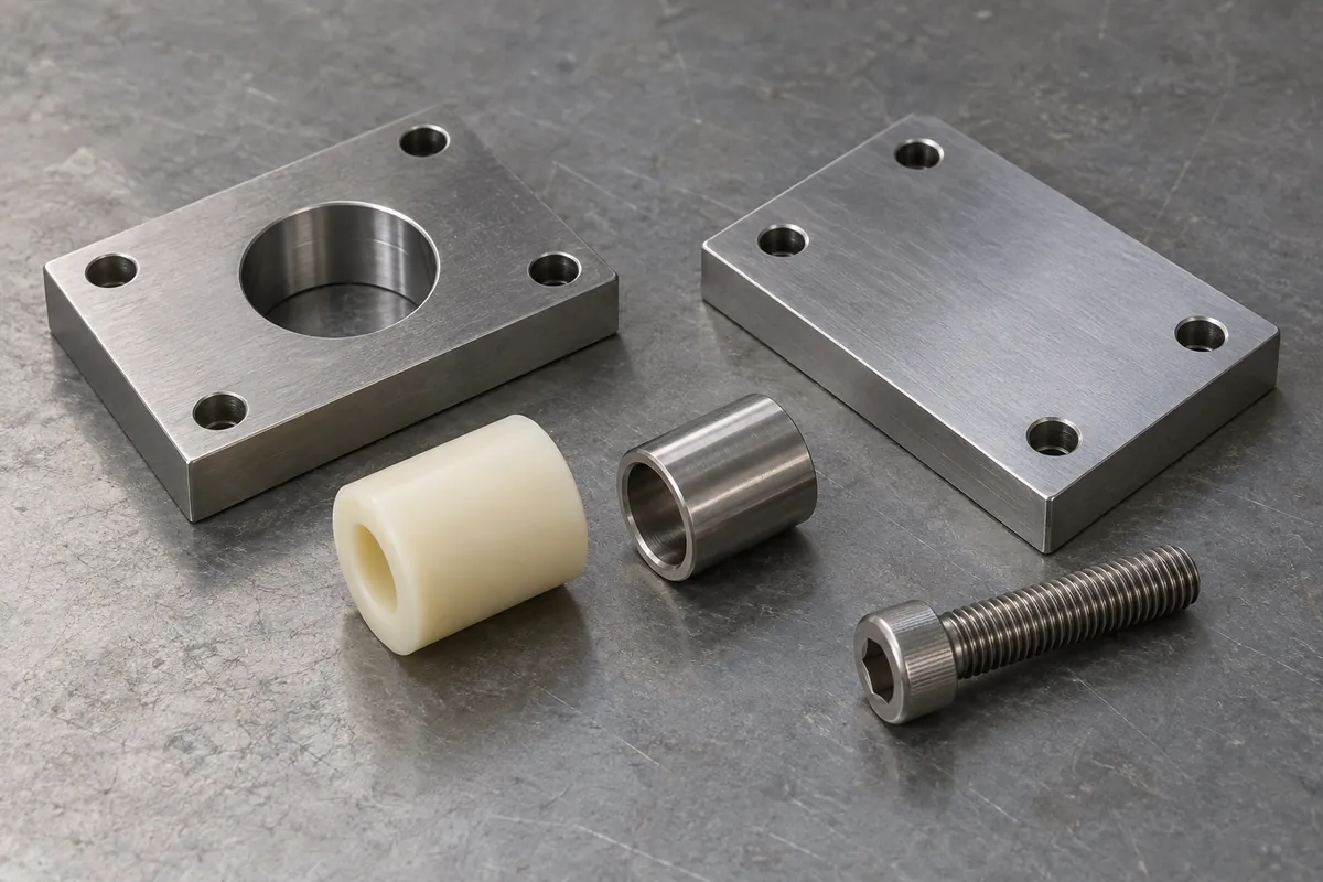
If the evaluation reveals unacceptable change, possible directions include a different grade, altered bearing area, a revised support geometry or a metal compression sleeve. Each changes more than one aspect of the assembly. A sleeve may redirect load, for example, while also affecting the dimensional chain, electrical separation and manufacturing sequence.
Retest the revised configuration against the same functional requirement. Do not accept a material substitution solely because it improves one datasheet property. If the design moves load away from the polymer, document where that load now goes and verify that the receiving component and its tolerances can support it.
For quoting, share the joint section, fastening definition and intended validation responsibility. The molding quotation should identify what will be inspected on the loose spacer and what must be checked on the assembled equipment. Clear boundaries allow the tooling and sample plan to support a meaningful engineering decision.
Discuss your custom spacer
Explore our custom injection-molded plastic spacers and standoffs. Send the drawing revision, mating components, material requirements and expected quantities. FECISION can review the molding and sample-approval scope; application ratings and final acceptance must follow the agreed project requirements.