

| Insert molding places a pre-formed metal, ceramic, or electronic component into an injection mold before plastic is injected. The molten plastic flows around the insert and locks onto its surface as it cools, creating a single permanently bonded part in one cycle. No adhesives, no secondary assembly, no separate fastening step. |
Think of it this way: an all-plastic threaded boss strips after a few reassembly cycles. An insert-molded brass thread handles the same loads indefinitely. The metal handles the mechanical work; the plastic provides the housing, the shape, and the weight savings.
The bond is mechanical, not chemical. As plastic cools, it shrinks slightly around the insert. Knurled patterns, grooves, and undercuts on the insert surface amplify this compressive grip into a joint capable of withstanding real engineering loads.
How Insert Molding Works — Step by Step
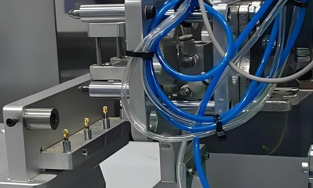
The Insert molding process runs on a standard injection molding machine, with one key addition: the insert must be positioned in the mold cavity before the injection cycle begins. Everything else follows the normal injection molding sequence.
1. Insert Preparation
Inserts are inspected for dimensional accuracy and surface condition. Knurls and threads must be clean — contamination prevents proper plastic bonding.
Large metal inserts (above roughly 50g) may be pre-heated to 150–200°C to reduce thermal shock when hot plastic contacts cold metal, lowering the risk of cracking in the surrounding plastic during cooling.
2. Insert Placement
The insert is loaded onto a core pin inside the mold cavity. At low volumes this is done by hand; at volumes above roughly 20,000 parts per year, robotic loading or vibratory bowl feeders provide the positioning repeatability (±0.05mm or better) that manual loading cannot consistently achieve.
3. Mold Closing
The mold halves close and clamp. The locating pin holds the insert in position against injection pressure, which can reach 40–140 MPa for engineering-grade plastics. Correct pin-to-insert fit is critical — too tight splits the insert, too loose allows it to shift.
4. Plastic Injection
Molten plastic fills the cavity, flowing around the insert and into every knurl groove, undercut, and through-hole. Gate location matters here: gating directly at the insert face causes a hydraulic jet that can displace it. Gates should feed the cavity away from the insert position.
5. Cooling and Solidification
As the plastic cools, it contracts slightly around the insert — creating a compressive mechanical grip. Metal inserts act as heat sinks, which can accelerate cooling in their immediate area. Balanced cooling channel design prevents differential shrinkage and warpage around insert locations.
6. Ejection and Inspection
The finished part ejects. Ejector pins must not push directly on the insert — any force applied to the insert during ejection risks pulling it out of the not-yet-fully-set plastic. Inspection checks insert position (CMM or vision system), pull-out force sampling, and dimensional conformance.
Insert Molding vs. Overmolding
The two terms appear together frequently, but they solve different problems. Insert molding integrates dissimilar materials (usually metal and plastic) in a single shot. Overmolding applies a second plastic material over a first plastic substrate — typically for soft-touch, sealing, or aesthetic purposes.
| Insert Molding | Overmolding | |
| What it does | Embeds a metal, ceramic, or pre-made component permanently inside molded plastic | Applies a second plastic material over an existing plastic substrate |
| Bond mechanism | Mechanical — plastic shrinks around knurls, grooves, and undercuts on the insert surface | Chemical + mechanical — requires compatible polymers at the interface |
| Primary use case | Structural: threaded connections, electrical contacts, bearing surfaces, sensors | Ergonomic and sealing: grips, soft-touch surfaces, integrated gaskets |
| Number of molds | One mold; insert is loaded before injection | Two molds minimum (substrate + overmold), or one two-shot tool |
| Cycle steps | One-shot process | Two-shot process — substrate first, then overmold |
| Material pairing | Metal + plastic (dissimilar materials — chemical bonding not required) | Plastic + plastic (chemical compatibility between layers required) |
| Example part | USB connector housing with brass contacts; nylon pump body with steel shaft | Power tool handle with TPE soft-grip over PP core |
Sometimes both processes are used on the same part — insert molding adds the metal structural element, then overmolding adds the soft ergonomic layer. Premium surgical instruments and high-end power tools are common examples.
For a detailed side-by-side comparison of both processes, see Fecision’s article on overmolding vs. insert molding.
Materials: Plastics and Insert Types
Material selection in insert molding involves two matched decisions: the insert and the plastic. They must be compatible not just in their engineering properties but in how they interact during the molding cycle — particularly regarding thermal expansion, shrinkage, and the plastic’s ability to flow into fine surface features on the insert.
Plastic Resins
Plastic choice depends on three categories: mechanical attributes and chemical and thermal demands.
| Material | Common Grade | Why It Works in Insert Molding | Typical Applications |
| Nylon (PA6/PA66) | Most common | Strong mechanical interlock with brass; semi-crystalline shrinkage grips knurl geometry tightly | Threaded housings, automotive connectors, industrial brackets |
| PA66-GF30 (glass-filled) | Medical/auto | Glass fibres lock inserts without thread deformation; Cpk 1.67+ achievable | Medical device housings, precision sensor brackets |
| ABS | Consumer goods | Good adhesion; lower temperature keeps insert thermal stress manageable | Electronics housings, consumer product enclosures |
| Polycarbonate (PC) | Electronics | Excellent dimensional stability around insert; slightly higher thermal stress than ABS | Connector bodies, optical device housings |
| PBT | Connectors | Low moisture absorption; stable after cycling in humid environments | Automotive connectors, relay housings |
| PEEK | Aerospace/medical | Exceptional mechanical strength; must pre-heat insert to avoid thermal cracking | Aerospace fastener inserts, implantable device components |
Insert Materials
Insert Molding makes use of various standard components, for which the material selections are:
| Material | Common Grade | Why It Works in Insert Molding | Typical Applications |
| Brass C36000/C37700 | Threaded inserts | Best machinability; resists corrosion without plating; good thermal conductivity during molding | Standard threaded bosses, M2–M10 range |
| Stainless 303/304/316 | Medical/food | Required for corrosive environments; 2–3× harder to machine than brass = higher insert cost | Medical device contacts, food-contact fittings |
| Aluminium (2024 grade) | Aerospace/portable electronics | 1/3 weight of brass; 40% stronger than brass; lead-free | Lightweight aerospace inserts, portable electronics |
| Copper | Electrical | Best conductivity for current-carrying contacts; soft — gripped well by most plastics | PCB contacts, bus bar inserts, grounding points |
| Ceramic | High-temperature | Withstands temperature extremes that would degrade metal; brittle — requires careful gate placement | Sensor elements, thermocouple housings |
A note on brass: Brass is by far the most common insert material for threaded connections. Grades C36000 and C37700 (free-machining brass) combine the easiest machinability of any insert material with good corrosion resistance, adequate thermal conductivity for mold cooling, and a thermal expansion coefficient closer to engineering plastics than stainless steel provides. This closer match reduces interface stress as both materials cool from melt temperature to room temperature — a practical reason why brass inserts last longer in cyclic service. [2]
Design Rules for Insert Molding (DFM)
Most insert molding failures are design failures, not process failures. The mold and machine can compensate for some poor design decisions — but not reliably. These six rules address the majority of first-article problems before steel is cut.
1. Minimum plastic wall thickness around the insert: 0.8mm, preferred 1.2–2.0mm
As plastic cools around a metal insert, thermal contraction creates hoop stress on the boss wall. A wall below 0.8mm lacks sufficient cross-section to contain this stress and will crack — sometimes immediately on ejection, sometimes after the first assembly cycle.
To put a number on it: for a 6mm outer-diameter brass insert in PA66, a 1.0mm wall can handle static loads but cracks under repeated torque cycling above 1.5 N·m. A 1.5mm wall raises the safe cyclic torque limit to approximately 3.5 N·m — more than double.
Our DFM review flags any boss wall below 1.2mm before tooling is approved.
2. Boss outer diameter: at least 1.5× the insert outer diameter
The boss must be large enough to contain the full knurl depth of the insert plus a minimum plastic wall. Its outer diameter at least 1.5 times the insert outer diameter as a practical starting point. [1] Smaller bosses concentrate hoop stress on a smaller cross-section and are more susceptible to cracking, especially in glass-filled materials.
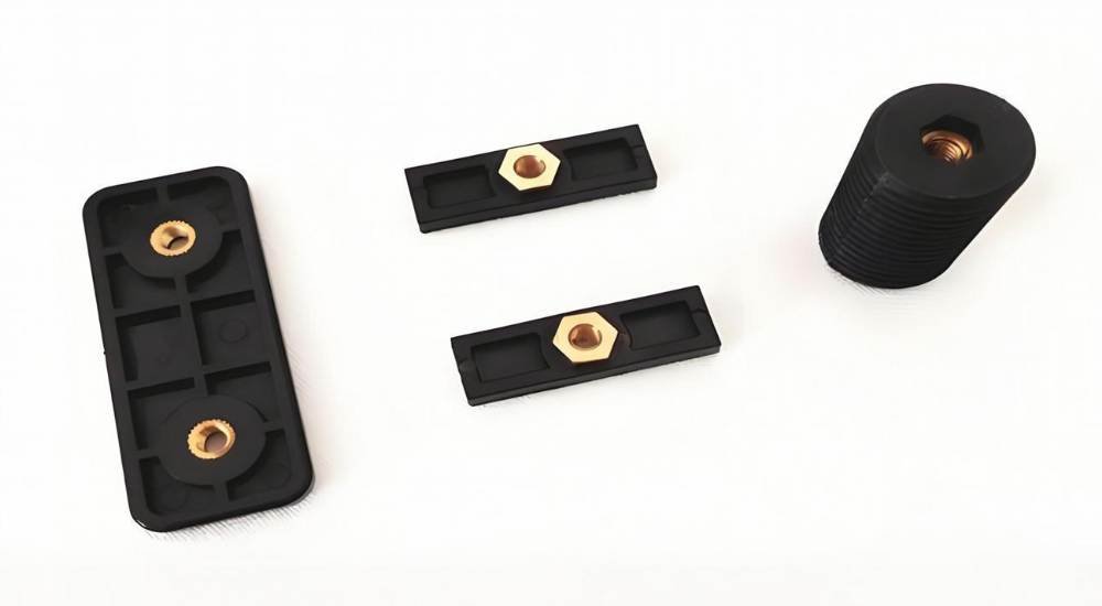
3. Insert surface features: knurls, grooves, and undercuts — not smooth
A smooth cylindrical insert relies entirely on compressive grip from the plastic’s shrinkage to resist pull-out and rotation. That force alone is insufficient for most service loads. Knurled patterns, annular grooves, and undercuts create mechanical interlocking that dramatically improves retention.
Diamond-knurl profiles achieve pull-out forces of 3.5–4.5 kN in PA66 for a 6mm insert — three to five times higher than a plastic-thread-only boss under the same conditions. Straight knurls improve torque resistance; helical knurls (30–45° angle) increase axial pull-out while reducing torque loss. Both can be combined on the same insert for optimised performance in both load directions. [2]
4. Gate placement: never directly at the insert face
Gating directly at an insert creates a high-velocity plastic jet that pushes the insert off its locating pin. Even a 0.5mm positional shift can result in insufficient plastic coverage on one side and compromised bond strength. Position gates to feed the cavity away from the insert — either to the side of the boss or on a balanced opposite wall.
5. Venting: 0.01–0.02mm depth at all end-of-fill zones near insert features
Knurls, undercuts, and the back face of inserts create dead-end flow regions where trapped air cannot escape. Trapped air produces burn marks, incomplete fill in the knurl channels, and weld lines behind the insert that are weaker than the surrounding material. Vents ground at the parting line near these regions allow gas to escape without allowing flash.
6. Pre-heat large metal inserts
Steel and brass are strong thermal conductors. A cold 50g steel insert in a 200°C plastic mold causes the plastic to solidify prematurely around the insert before the cavity fills — producing voids, incomplete encapsulation, and weak bond zones. Pre-heating the insert to 150–200°C before loading slows the temperature gradient and gives the plastic time to fill every surface feature before it freezes.
Advantages of Insert Molding
The advantages provided by insert molding surpass those of traditional manufacturing techniques include:
1. Pull-out strength that plastic threads simply cannot match
Threaded holes in unreinforced plastic strip after a handful of assembly cycles. A brass insert in the same housing — injection molded, not heat-staked — handles the same torque indefinitely. The difference is typically 3–5× in pull-out force.
The mechanism: plastic shrinks onto the insert’s knurl geometry as it cools, creating compressive engagement at every knurl ridge. When you tighten a screw, the torque is resisted by the metal-to-plastic interlock across the full knurl depth — not just surface friction.
2. One cycle, no secondary assembly
The alternative to insert molding is usually: mold the plastic part, then press, heat-stake, or ultrasonically insert a fastener. That is two process steps, two stations, two inspection points, and two opportunities to damage the part.
Insert molding eliminates all secondary operations. The finished bonded assembly comes out of the mold in a single cycle. At high volumes, the labour saving is significant.
3. Reduced part weight versus all-metal designs
Replacing a machined metal housing with an insert-molded plastic housing typically cuts weight by 40–60%. Nylon is approximately 7× lighter than steel by volume. For automotive, aerospace, and portable electronics, this is not a minor benefit — it directly affects fuel economy, payload capacity, and user comfort.
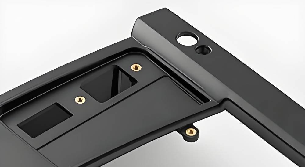
4. Hermetic sealing around embedded components
When an electrical contact or sensor must be sealed from moisture, chemicals, or pressure, insert molding is one of the most reliable methods available. The plastic completely encapsulates the insert, closing every potential ingress path in a single cycle without adhesives or gaskets.
Medical IV connectors and IP-rated connector housings are common examples — the plastic seal is formed by injection pressure, not by a downstream sealing step.
5. Material properties where they are actually needed
Insert molding lets each material do the job it does best. Brass handles threaded load. Polycarbonate handles the housing geometry and electrical insulation. Copper handles conductivity. The result is a part lighter, smaller, and more cost-effective than an all-metal design — but stronger where it counts than an all-plastic one.
Where Insert Molding Is Used — Applications by Industry
Electronics and Connectors
This is arguably the largest application volume for insert molding globally. USB connectors, audio jacks, power connectors, PCB standoffs, and antenna contacts all use insert-molded copper or brass contacts within a plastic housing.
The combination of electrical conductivity from the metal and insulation from the plastic is precisely what the electronics and connectors application requires — and cannot be achieved with either material alone.
Medical Devices
Catheter hubs, surgical instrument handles, infusion pump components, and implantable device housings all rely on insert molding. Medical insert molding programs typically use PA66-GF30 (glass-filled nylon) or PEEK for the plastic, and 316 stainless steel for the insert — meeting both biocompatibility requirements and the repeated sterilisation cycling that medical devices must withstand.
Position accuracy is particularly critical in medical applications — a misaligned insert can compromise device function or patient safety. CMM verification with position Cpk above 1.67 is standard for Class II and III device programs.
Our Related service: Fecision medical injection molding
Automotive
Automotive insert molding covers a wide range: threaded fastener bushings in dashboard assemblies, sensor housings with embedded contacts in engine management systems, and structural brackets that use aluminium inserts within glass-filled nylon frames to meet weight and load targets simultaneously.
Aerospace and Defence
Lightweight structural inserts — aluminium 2024 grade, typically — are molded into PEEK or high-performance nylon housings in aerospace programs where every gram of weight reduction has economic value. The insert provides the load-bearing thread for structural fasteners; the PEEK provides chemical resistance, high-temperature stability, and weight reduction versus an all-metal component.
Consumer Products
Power tool handles with metal shaft interfaces, kitchen appliance knobs with embedded brass threads, and fitness equipment components with metal pivot inserts all use insert molding. The combination of plastic design freedom and metal durability is the common theme — neither material alone achieves what the application requires at a commercially viable cost.
Frequently Asked Questions
How much stronger is an insert-molded thread versus a tapped plastic thread?
Typically 3–5× stronger in pull-out force. A brass threaded insert in PA66 achieves 3.5–4.5 kN pull-out; a tapped plastic boss in the same material achieves 0.8–1.2 kN. The difference is larger in torque resistance, where plastic threads strip progressively during repeated assembly while metal threads remain stable.
Does insert molding work with all thermoplastics?
Most engineering-grade thermoplastics process well with insert molding. The practical limitations are at the extremes of processing temperature. Very high-temperature plastics like PEI (Ultem) or unreinforced PEEK require barrel temperatures above 370°C, which creates aggressive thermal shock for large metal inserts. At the other end, highly flexible materials like pure TPU or silicone rubber provide limited compressive grip around inserts.
What causes insert shift during molding, and how is it prevented?
Insert shift is caused by the hydraulic pressure of the plastic melt pushing the insert off its locating pin before it has time to be gripped by solidifying plastic.
- The three main contributors are: gating directly at the insert face, insufficient locating pin diameter (too loose a fit), and excessively high injection speed.
- Prevention: gate away from the insert, size the locating pin to provide firm positive location (the insert should not rattle on the pin), and use a moderate fill rate with a slow initial injection stage until the insert is surrounded by partially solidifying plastic.
How is insert position verified in production?
Depending on volume and tolerance requirements, verification ranges from periodic manual pull-out force sampling to 100% in-line vision inspection. For medical devices and aerospace components, automated vision systems check insert position every cycle. CMM measurement on a sampling basis is standard for automotive programs.
What is the minimum production volume that justifies insert molding tooling cost?
There is no universal answer, but a practical starting point:
- If production volume is below 5,000 parts per year and the design is still evolving, post-mold insertion methods (heat-staking or ultrasonic) typically offer better economics.
- Above 20,000 parts per year, insert molding’s per-part cost advantage — one cycle instead of two steps — usually justifies the tooling investment.
- Between 5,000 and 20,000, the decision depends on insert complexity, required bond strength, and whether automated loading can be justified.
Insert Molding at Fecision
Fecision’s injection molding capability covers both manual and robotic insert loading, across brass, stainless, aluminium, and copper inserts from M2 to M10 in standard thread sizes. All insert molding programs include a DFM review before tooling: wall thickness, boss geometry, gate placement, and insert surface specification are confirmed against the requirements before steel is cut.
- Tooling: In-house CNC machining and slow-wire EDM for high-precision mold features, ±0.002mm CMM inspection on all insert-molded first articles.
- Medical programs: ISO 13485:2016 quality management system, full lot traceability from insert material COA to finished part documentation. Cleanroom production for Class II and III device components.
- Certification: ISO 9001:2015, ISO 13485:2016, AS 9100 Rev D.
Submit a drawing for DFM review at fecision.com/contact-us. Contact us to discuss all aspects of your insert molding requirements.
Conclusion
Multiple industry sectors achieve better product resistance and economical benefits through the insert molding manufacturing method, which also provides sophisticated design elements. Product victory in the automotive, medical devices, electronics, and aerospace industries depends on the appropriate selection of an insert moulding partner.
Fecision provides top-tier insert injection molding solutions that comply with every existing industry requirement. Contact us to discuss all aspects of your insert molding requirements.
References & Authoritative Sources
Accessed April 2026.
[1] Protolabs Design Tips. ‘Building Strength into Parts with Insert Molding.’ https://www.protolabs.com/resources/design-tips/building-strength-into-parts-with-insert-molding/
[2] SPIROL International. ‘Threaded Inserts for Plastics — Design Guide.’ https://www.spirol.com/assets/files/ins-threaded-inserts-design-guide-us.pdf


