
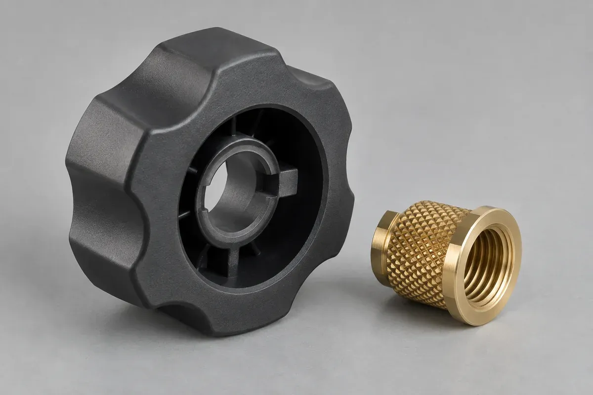
Product design illustrations. Final geometry, materials and acceptance criteria are project-specific.
A metal insert can provide a useful interface inside a plastic control knob, but it does not make the surrounding plastic irrelevant. Torque and axial loads still have to pass through the insert-to-plastic joint. That joint needs its own design definition and acceptance evidence.
Start by identifying why the insert is present. It may provide a thread, a controlled shaft interface or another required feature. Different functions create different loads and installation constraints. Avoid selecting an insert solely because its outside diameter fits the available cavity.
Trace the loads through the complete knob
Follow the operating load from the grip surface through the plastic body, insert and shaft. Look separately at torque, axial pull and any loads introduced during assembly. The weakest interface may not be the metal feature that is easiest to specify.
For a side-screw design, include the local reaction from tightening. For a threaded mounting arrangement, include the intended fastening sequence. These are design inputs for the responsible engineer, not universal ratings that can be inferred from the insert's appearance.
SPIROL's insert design guide distinguishes rotational and axial retention considerations. That distinction is useful for planning knob checks: a pull-out observation and a torque observation answer different questions about the joint.
Make the insert definition unambiguous
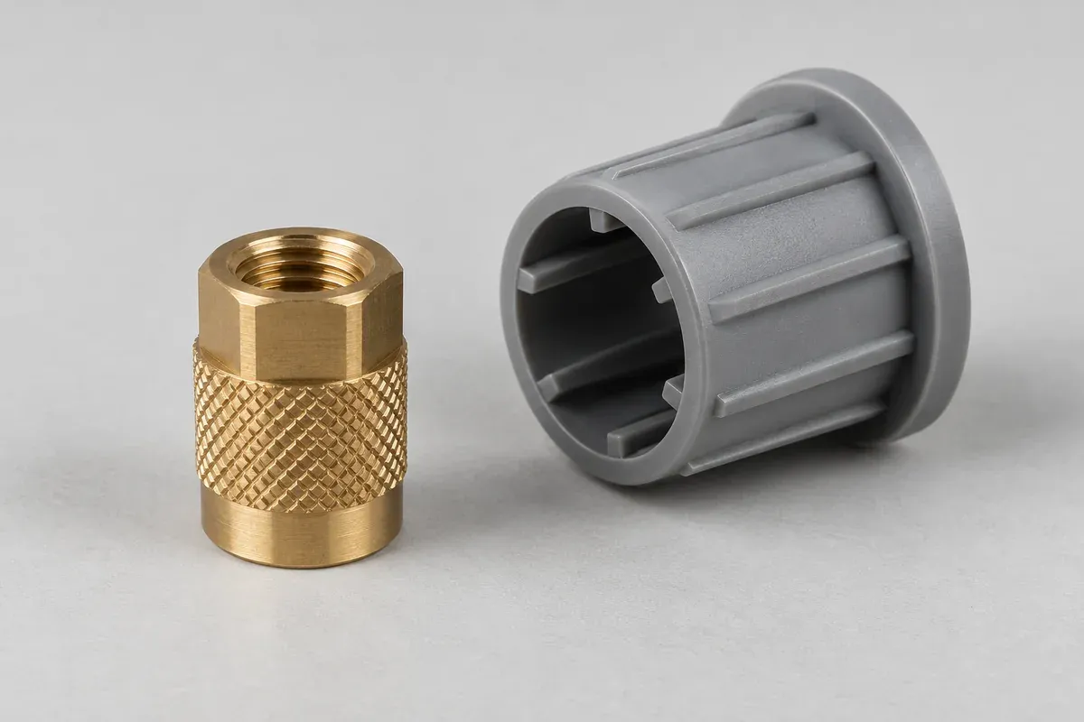
Provide the controlled insert drawing, material and finish, including the features that interact with the plastic. State whether the insert is supplied by the customer or included in the molding supplier's order. A generic threaded insert description leaves too many purchasing assumptions open.
Define the insert's position and orientation relative to the knob. Concentricity, exposed length and the relationship to an index mark may have different functional importance. Identify the required references instead of relying on the external grip shape as an informal locating surface.
If the insert has an orientation-sensitive feature, show how it will be loaded and checked. A component that can physically enter the tool or fixture in more than one position needs a deliberate assembly-control approach.
Review the surrounding plastic and tool access
The boss, ribs and neighboring walls must be reviewed with the selected resin and molding process. Adding material around an insert is not a complete design method. The change can affect filling, local appearance, cooling and the available space for the shaft.
Discuss the proposed installation route. Molded-in, heat-installed and other post-molding methods have different requirements for the receiving geometry and process. Do not transfer a hole specification from one route to another without the insert manufacturer's guidance and a component review.
Identify surfaces that must remain free of plastic or installation damage. A thread that is obstructed or distorted can invalidate the joint even when the insert appears correctly seated. Include these local conditions in the acceptance drawing or referenced standard.
Use an agreed specimen and fixture for evaluation
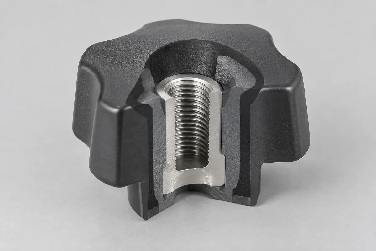
Evaluate the actual selected resin, insert and installation method in representative samples. Record the sample condition and process identity. A hand-fitted development insert in a modified prototype should not silently become evidence for the production joint.
Design the fixture so it applies the intended load without introducing an unrelated failure. Gripping a thin decorative skirt can test the skirt rather than the insert interface. Define the support and load path before interpreting the result.
Keep the torque and pull-off acceptance plan separate from routine dimensional checks. If the application requires environmental exposure or repeated operation, its effect on the joint must be evaluated under the agreed conditions.
Quote the joint, not an unspecified extra
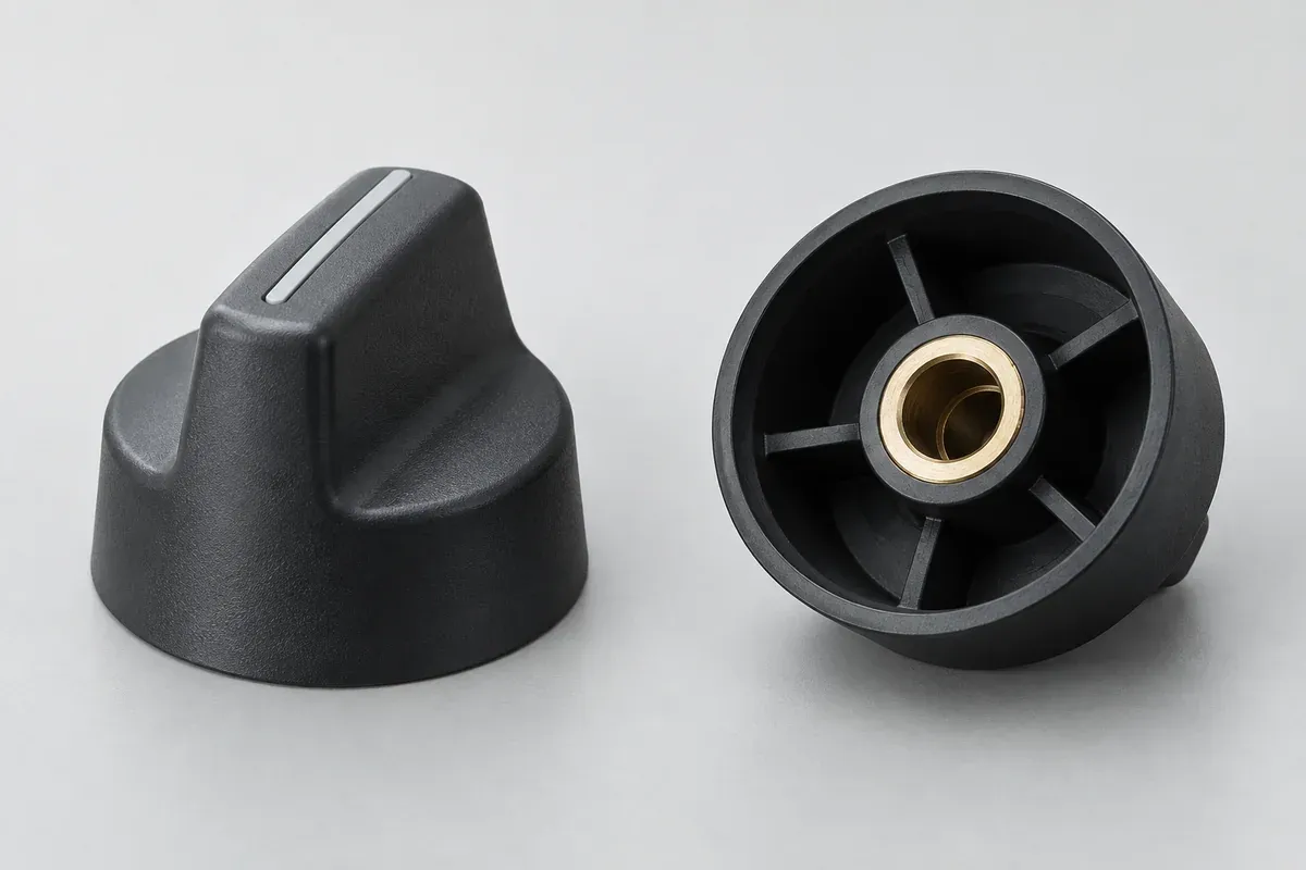
Ask the proposal to identify insert supply, loading or installation, tooling, inspection and rejection responsibility. State which sample evidence is included and which evaluation remains with the product owner. This makes comparisons more meaningful than a bare molded-part price.
Changes to insert geometry, resin grade or installation method should follow an agreed review path. A substitute that preserves the internal thread can still change the external retention features. Preserve the complete approved configuration in the production record.
For the broader mounting decision, compare push-on and set-screw knob concepts. An insert is one part of that decision, not an automatic requirement for every control knob or a substitute for a defined shaft interface.
Turn the review into a defined molding scope
Explore our custom injection-molded control knobs and the related illustrative engineering study. Send the drawing revision, counterpart details, intended use and the decisions still open. Development samples and production approval should have separate, agreed deliverables.