
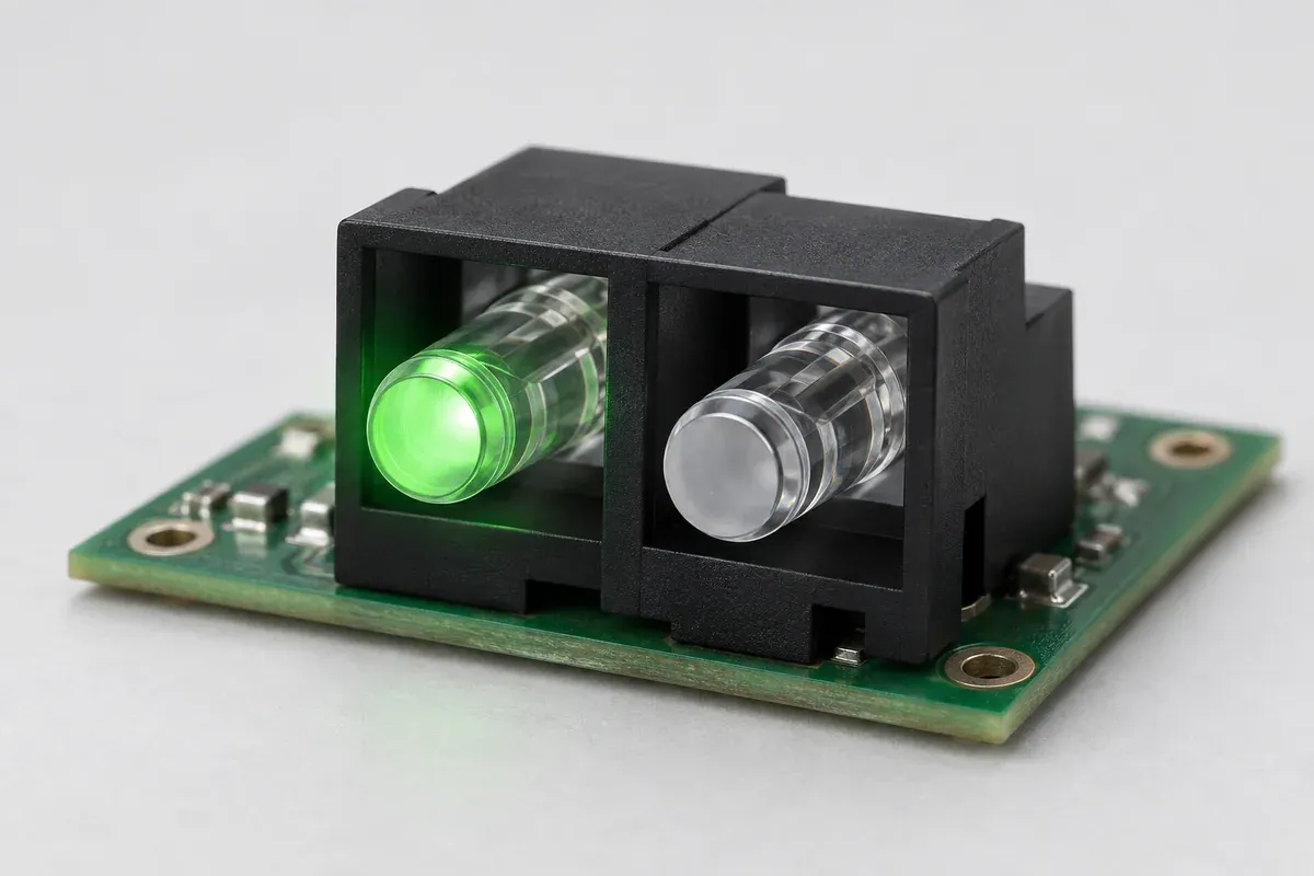
Product design illustrations. Final geometry, materials and acceptance criteria are project-specific.
A neighboring indicator can look faintly active even when its LED is off. That is a functional problem when the two windows represent different states, not merely a cosmetic defect in a transparent part. Increasing LED drive may make the intended window brighter while making the unintended indication more obvious. Start by identifying the light path that reaches the wrong window.
This review concerns adjacent status indicators, not a general illumination panel. Its aim is a defined separation between the intended states under specified viewing conditions. It does not promise zero leakage from a particular wall color, material name or nominal spacing.
Locate the unwanted path before adding a barrier
Inspect the entrance region first. Light emitted outside the intended guide can reach a neighboring entrance or travel through open space around the carrier. Look at LED position, the source's emission pattern and the gap between the source and its guide. A wall that separates the upper stems may do little if both LEDs illuminate a common open cavity below it.
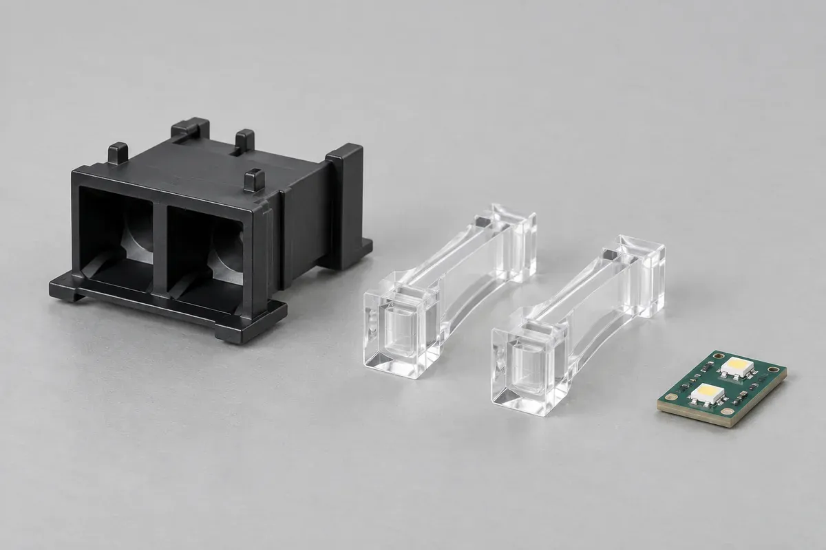
Next inspect connections between the transparent parts. A molded clear bridge can be mechanically convenient while creating an optical connection that must be evaluated. Separate stems held by an opaque carrier are a different architecture, not an automatic substitute with identical assembly cost and tolerance requirements.
Finally inspect the exit and panel. Light can escape around a guide, through a thin panel region or through a gap at the bezel. The visible symptom may appear at the front even when the unintended route began behind the board. Trace the whole assembly rather than assuming the clear component alone is responsible.
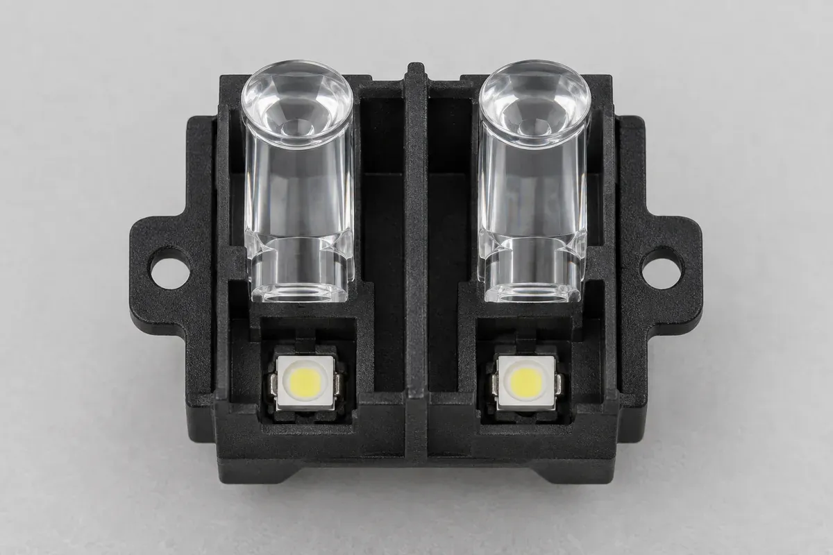
Use an opaque region as a designed component
Bivar's light-pipe application overview discusses light bleed and the role of isolation around individual indicators. The relevant principle is to control unintended transmission as well as collect useful light. It does not provide a universal wall thickness or qualify a custom assembly.
Specify the actual carrier material, color and wall geometry. A black-looking thin wall is not necessarily sufficiently opaque at the LED wavelength and drive condition. Likewise, a continuous wall in CAD may acquire an assembly gap when the board is displaced or the housing closes unevenly. Include manufacturing variation and the real joints in the review.
Consider how the carrier is retained and located. If it floats relative to the LEDs, a barrier can partially obstruct the intended entrance at one extreme and expose an unintended path at another. Optical isolation and mechanical location therefore need a shared drawing reference, rather than separate sketches with unrelated nominal positions.
| Region | Question | Useful comparison |
|---|---|---|
| LED entrance | Can a source illuminate the adjacent entrance through open space? | One LED active at a time, with the specified source and locating range. |
| Guide body | Is there a clear bridge or other unintended connection? | Alternative path geometries with source and viewing conditions held constant. |
| Carrier joint | Does the barrier remain continuous after assembly? | Assembled counterparts, including permitted position and closure variation. |
| Panel exit | Can light bypass the window or mask? | Final panel, bezel and visible opening rather than an uncovered bench sample. |
Keep assembly access in the isolation proposal
A barrier must still allow the board, carrier and panel to be assembled in the planned sequence. Check lead-in features, component keep-outs and the motion required to seat the guides. Do not use the LED package as a hard stop to compensate for an undefined support height. An optical improvement that requires uncontrolled assembly force is not a closed design.
At a right-angle path, identify where the carrier supports the guide and where surfaces need clearance. A support that contacts a critical optical region can change the behavior being evaluated. The tooling review should identify those surfaces rather than describe every outer face as equally available for retention or ejection.
Test states, not just a fully illuminated photograph
Operate each indicator separately, both together where relevant, and both off under the agreed ambient light. Record which window is expected to appear active in each state. If colors differ, include their actual sources and operating conditions; one convenient white LED is not automatically a representative substitute.
Specify observation distance, viewing direction, ambient illumination and the acceptance method. A camera on automatic exposure can change the apparent brightness of a dark neighboring window between shots. Photographs are useful records when their setup is controlled, but they should not silently replace an agreed visual or instrument-based criterion.
If masking one suspected route changes the symptom, record that as an investigative result for that setup. Temporary tape, added foam or a manually modified divider changes the configuration. A promising trial needs translation into a manufacturable feature and a repeat evaluation of the proposed production assembly.
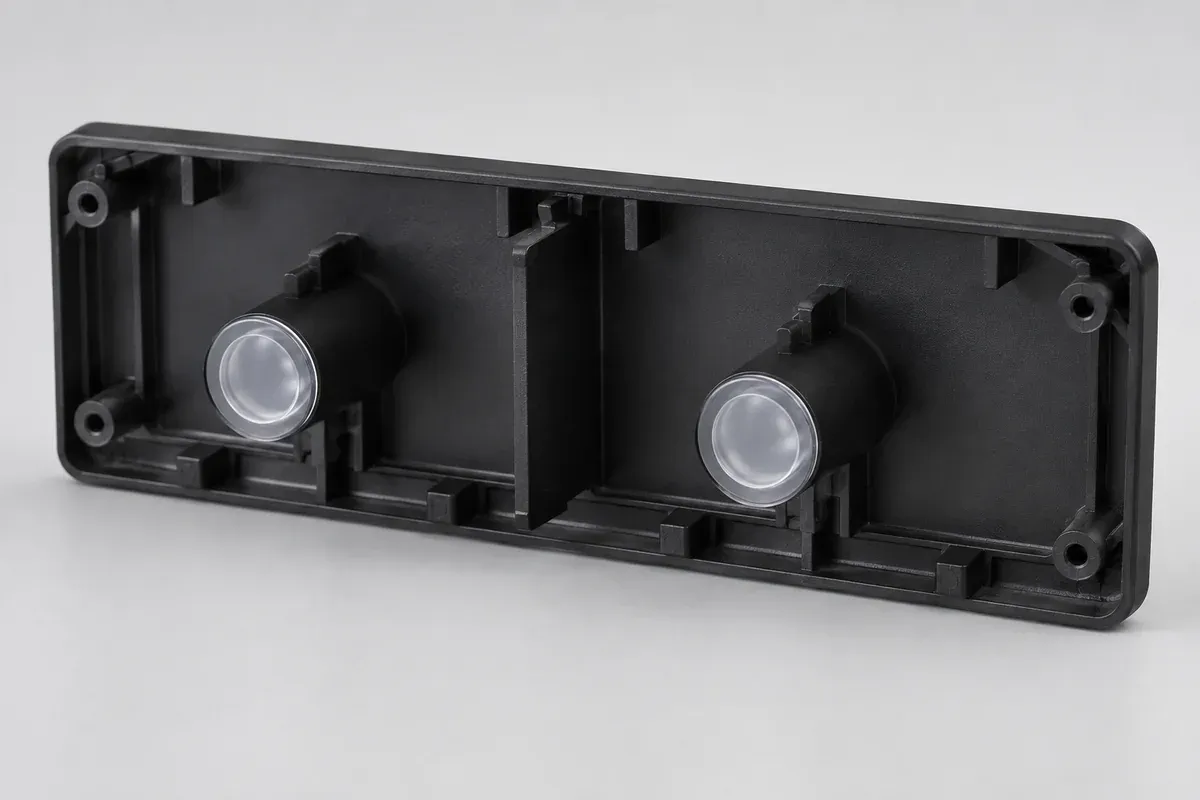
Read the gap and alignment guide when a leak changes with board position, and the sample acceptance guide when different reviewers disagree about the same indicator. A useful outcome is an agreed state distinction and a controlled assembly, not an unsupported claim of perfect isolation.
Turn the review into a defined molding scope
Explore our custom injection-molded LED light pipes and the related illustrative engineering study. Send the drawing revision, counterpart details, intended use and the decisions still open. Development samples and production approval should have separate, agreed deliverables.