

| Small part injection molding produces plastic components typically under 10 grams using specialized machines, tooling, and process controls that standard injection molding cannot provide. The key differences: micro-screws (14–18 mm diameter) for precise milligram-range metering, ultra-high injection velocities (up to 1,000 mm/s) to fill thin sections before freeze-off, tolerances to ±0.01 mm, and 100% automated inspection instead of sampling. |
This guide explains what makes small part injection molding technically distinct, covers the materials best suited to micro-scale production, documents the tolerance framework engineers should apply, and walks through the five production phases.
What Is Small Part Injection Molding?
Small part injection molding — also called micro molding when shot weights fall below approximately 1 gram — is a specialized manufacturing process for producing plastic components with dimensions in the millimeter range, feature sizes below 1 mm, and shot weights from 0.1 g to roughly 10 g.
The process uses the same fundamental physics as standard injection molding: molten polymer is injected under pressure into a precision mold, cooled, and ejected. But at micro scale, engineering constraints that are manageable at standard scale become critical.
Filling a 0.2 mm wall section before the melt front freezes requires injection velocities up to 1,000 mm/s — an order of magnitude faster than standard molding. Gate sizes of 0.15–0.5 mm mean that any contamination or wear causes dimensional drift that propagates directly into part geometry.
How Small Is ‘Small Part’?
The industry uses overlapping terminology. ‘Small part moulding’ generally refers to components under 10 grams and under 50 mm in their largest dimension. ‘Micro moulding’ is typically used for components under 1 gram and feature sizes in the 0.01–0.5 mm range — the regime where shot weight can be less than the weight of the runner system.
A practical marker: when the runner system (sprue, gates, runners) outweighs the finished part, a hot runner or direct-gate system is no longer a cost-optimization — it is a process requirement. Cold runner waste of 10× the part weight is economically and practically unsustainable at any meaningful production volume.
Small Part vs Standard Injection Molding: Key Differences
Engineers new to small-part programs often discover late in development that standard injection molding equipment and process knowledge do not translate directly to micro-scale production. The table below maps the specific parameters where the two processes diverge — and why each difference matters.
| Parameter | Standard Injection Moulding | Small / Micro Part Moulding |
| Shot weight | Standard: 10–1,000+ g; shot weight dominates screw selection | Small / micro: 0.1–10 g; runner can outweigh the part — hot runner or direct-gate essential above 5,000 parts |
| Screw diameter | Standard: 25–60 mm; provides stable plasticisation over large volumes | Micro: 14–18 mm; shorter residence time, lower shear, precise metering of milligram-range shots |
| Injection velocity | Standard: 50–200 mm/s typical | Micro: up to 750–1,000 mm/s to fill thin sections before freeze-off — requires all-electric servo drives for control fidelity |
| Tolerances | Standard: ± 0.1–0.3 mm readily achievable | Micro: ± 0.01–0.025 mm on critical features; each micron of cavity steel deviation translates directly to part deviation |
| Cooling time | Standard: 10–60 s (wall-thickness driven) | Micro: 2–8 s for thin walls; conformal cooling channels often mandatory to reach every corner of complex micro-cavities |
| Gate size | Standard: 0.8–3 mm diameter | Micro: 0.15–0.5 mm; undersized gates create shear heating that degrades material at melt temperatures even within the barrel setpoint range |
| Ejection | Standard: ejector pins 2–8 mm diameter push the part | Micro: pins as small as 0.5 mm; fragile parts may need air eject or robotic extraction to avoid distortion or surface marking |
| Inspection | Standard: periodic CMM sampling and visual inspection | Micro: 100% automated vision inspection plus offline CMM on critical dimensions; human eye cannot reliably detect defects at micron scale |
The most consequential difference for program planning: tolerance achievability. General injection moulding tolerances of ±0.1 mm are ‘readily achieved’ across a range of part geometries. At micro scale, ±0.025 mm on a critical feature requires a dedicated process development effort — validated tooling steel tolerances, Cpk verification on first-article samples, and a defined monitoring frequency for production. [1]
Why Dimensional Precision Determines Small Part Performance
At micro scale, the relationship between dimensional accuracy and functional performance is direct and unforgiving. Tolerances that represent minor cosmetic variation at standard scale represent complete functional failure at micro scale.
Critical Function in Assembled Systems
A micro-gear in a drug delivery pump metering 0.1 µL per step requires gear pitch accuracy within a few microns. A dimensional error of ±0.1 mm — acceptable on a standard enclosure — represents a full pitch error on a 0.3 mm pitch gear, causing missed doses or over-delivery. Medical and aerospace applications offer no margin for this kind of failure because the consequence is patient harm or system failure, not a warranty return.
Assembly Interchangeability and Tolerance Stackup
Small parts rarely function alone — they assemble into systems. Each part’s dimensional variation accumulates through the assembly stack. Per ASME Y14.5 and ISO 1101, this ‘tolerance stackup’ must be analysed before tolerances are finalised on individual parts.
A practical example: three connector components each with ±0.05 mm position tolerance can produce a combined positional error of ±0.15 mm in the worst case — potentially preventing engagement. Identifying this in simulation before tooling is cut costs nothing. Discovering it in physical assembly costs a tool modification and 4–8 weeks. [2]
Material Property Realization
High-performance resins like PEEK, LCP, and PPS deliver their specified mechanical properties only when processed within tight parameter windows. LCP requires barrel temperature control within ±5°C and injection timing within milliseconds to achieve the molecular orientation that produces its low-shrinkage dimensional stability.
Processing outside these windows produces parts that measure within tolerance but fail mechanically in service — because the crystallinity, fiber orientation, or residual stress state is wrong. The material’s data sheet properties assume a validated process. Precision molding is what converts material specification into part performance.
Regulatory and Safety Compliance
Medical implants, aerospace connectors, and automotive safety sensors must validate dimensional stability under cycling conditions — thermal cycling per USCAR-2, sterilization cycling per ISO 11135/11137, or mechanical fatigue per device-specific test protocols. Precision molding provides the documented Cpk data and process validation records that regulators require.
Specifically for medical small parts: ISO 13485:2016 Clause 7.5.6 classifies injection molding as a ‘special process’ — one whose output cannot be fully verified by downstream inspection alone. This makes process validation (IQ/OQ/PQ) with Cpk demonstration mandatory, not optional.
The Five Phases of Precision Small Part Injection Molding
Creating small parts requires a rigorous, step-by-step approach to engineering. Each phase below addresses a specific failure mode unique to small-part production. The sequence is not arbitrary — each phase builds the conditions that the next phase requires.
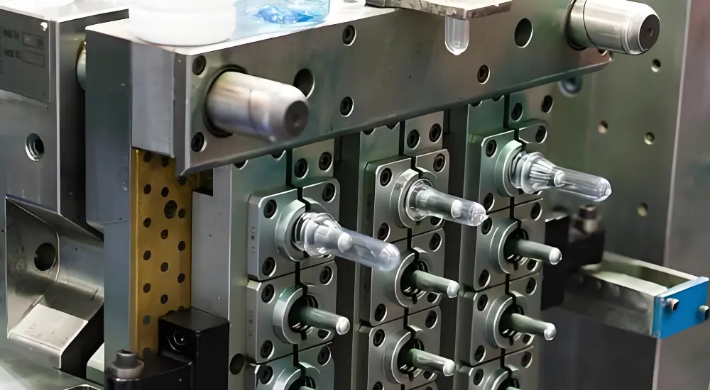
Phase 1: Micro-Precision Mold Design
Utilize advanced machining and mold flow simulation to build high-precision molds to ensure molten plastic will flow smoothly into every tiny area of the tool.
Micro-Cavity Architecture
Mold cavities for small parts are machined by high-speed CNC and EDM to tolerances of ±0.003–0.005 mm on critical features. This is 5–10× tighter than general mold machining and requires specialized toolpath strategies, slow-wire EDM for fine features, and CMM verification of cavity geometry before first steel is released for trial.
Intelligent Thermal Management
Mold flow simulation (Moldex3D or equivalent) is mandatory before cutting steel. At micro scale, gate location errors that would produce a cosmetic weld line at standard scale instead produce a structurally weakened parting plane or a short shot — because the thin section freezes before the weld line can heal.
Balanced thermal design is critical because it eliminates differential shrinkage. Conformal cooling channels into the mold insert can maintain cavity surface temperature uniformity within ±2°C, preventing differential shrinkage across the part.
Phase 2: Material Preparation and Qualification
Select the right polymers and prepare them in a controlled environment to prevent contamination and maintain consistent mechanical properties throughout production.
High-Performance Resin Matching and Pre-Processing
Hygroscopic resins — nylon PA66, PET, PC, PEEK — absorb atmospheric moisture that converts to steam at barrel temperatures. The result is splay marks, voids, and degraded mechanical properties.
Drying protocols are non-negotiable: PA66 to < 0.2% moisture, PC to < 0.02%, PEEK to < 0.02%. Gravimetric dosing units meter additives — colorants, glass fibre — with laboratory accuracy, batch to batch, which is vital when you are producing small parts injection molding components that require uniform color and strength.
Material Lot Tracking
For materials like LCP, material lot tracking is essential: lot-to-lot variation in LCP melt flow index can shift shrinkage by 0.02–0.05%, which translates directly to dimensional drift at micro tolerances. Fecision records resin lot number against every production batch for full material traceability.
Phase 3: Machine Setup and Closed-Loop Control
Advanced all-electric machines, utilizing extreme pressure control with real-time monitoring, create the necessary mechanical accuracy for high-speed delivery of micro-sized shot plastics.
Electric-Driven Micro Screw Technology
All-electric injection presses with 14–18 mm micro-screws are the production standard for small parts. The small screw diameter allows precise metering of milligram-range shots — a standard 30 mm screw cannot meter sub-gram shots with the repeatability required for micro-tolerance production. Servo-driven injection provides the millisecond timing accuracy and velocity profiles that thin-wall filling requires.
Cavity Pressure Real-Time Adjustment
In-cavity pressure sensors provide shot-to-shot feedback. If a gate begins to wear and flow resistance increases, the cavity pressure drop registers immediately — allowing adaptive control to compensate or triggering a process stop before out-of-tolerance parts accumulate. This closed-loop approach is what maintains Cpk ≥ 1.67 across long production runs without increasing operator monitoring frequency.
Phase 4: Controlled Fill, Pack, and Solidification
Controlling how the plastic flows during the injection mold process assists in the maintaining of an even cooling rate on the component so that no internal stress, defects, or warpage occur.
Multi-Stage Velocity and Pressure Management
Multi-stage velocity profiles fill thin sections at maximum velocity — to prevent premature freeze-off — then slow as the cavity nears full to prevent overpacking and flash. The transfer from injection to pack pressure is timed to within milliseconds of gate freeze-off, controlled by cavity pressure signal rather than operator-set switchover.
Solidification and Thermal Balancing
Hold pressure duration is calibrated specifically to compensate for the material’s volumetric shrinkage during solidification — without overpacking micro-features that would distort under excess pressure. Balanced cooling circuits keep temperature even across the mold surface, preventing the differential shrinkage that causes warpage in thin-walled small components.
Phase 5: Ejection, Inspection, and Traceability
Robotic systems and digital sensors handle the finished parts to guarantee quality and provide a complete record of production for every batch.
Precision Robotic Extraction
Robotic extraction handles parts that cannot be contacted by human hands without deformation or contamination. Ejector pins as small as 0.5 mm are positioned on non-cosmetic structural features — direct pin contact on a micro-lens surface or a 0.1 mm wall would mark or distort the part during ejection.
100% Automated Verification
100% automated vision inspection scans for surface defects and dimensional deviations at production speed. Offline CMM measurement verifies critical dimensions on first-article and statistically sampled production batches, generating the dimensional data record required for IQ/OQ/PQ program completion. Full batch traceability — resin lot, machine ID, process parameters, inspection results — is maintained for every production order.
Material Selection for Small Part Injection Molding
Material choice for small parts involves constraints that do not apply at standard scale. Very low shrinkage is critical — even a 0.5% shrinkage difference between materials translates to 0.005 mm on a 1 mm feature. Processing temperature must be compatible with the micro-screw system. And for medical or food-contact applications, biocompatibility data per ISO 10993 or FDA 21 CFR must accompany the material.
| Resin | Typical Shrinkage | Screw Requirement | Engineering Notes for Small Parts |
| LCP (Liquid Crystal Polymer) | < 0.1% | 14–18 mm micro-screw | Lowest shrinkage of any injection-mouldable resin — delivers the tightest as-moulded tolerances. Wall sections to 0.2 mm achievable. Rapid solidification at the flow front demands gates within 150 mm of the furthest feature. Standard for 0.3–0.5 mm pitch micro-connectors and intraocular lens haptics. |
| PEEK | 1.0–1.3% | Standard micro-screw; barrel 360–400°C | High stiffness (3.6 GPa), biocompatible, autoclave-stable. Demanding processing temperature requires heated tooling. Used for implantable device micro-housings, surgical instrument tips, and aerospace micro-bushings. |
| PPS (Polyphenylene sulfide) | 0.5–0.7% (GF grade) | Standard | Continuous service to 220°C, UL 94 V-0. Glass-filled grades reduce shrinkage but introduce anisotropic shrinkage — simulate before tooling. Used for sensor housings and high-temperature automotive micro-connectors. |
| PC (Polycarbonate) | 0.5–0.7% | Standard | Optical clarity for lens and sensor window components. Impact resistance sufficient for thin-wall micro-enclosures. Autoclave-limited (~15 cycles). Standard for medical diagnostic components and wearable sensor housings. |
| POM (Acetal / Delrin) | 1.8–2.5% | Standard | Excellent self-lubrication and stiffness for precision gears and micro-valve components. Higher shrinkage requires mould-flow simulation to predict warpage. Do not combine with PVC in the same machine — violent reactive decomposition. |
| PA66-GF30 (Glass-filled nylon) | 0.3–0.8% | Standard | High stiffness and insert grip. Pre-dry to < 0.2% moisture. Used for micro-connector housings, instrument brackets, and drug delivery device body structures. |
Why LCP leads for micro-molding: LCP’s shrinkage below 0.1% — compared to 1.5–2.5% for commodity resins — means that mold steel dimensions translate almost directly to part dimensions. This makes first-article validation faster, tooling correction less frequent, and production Cpk higher.
Tolerance Framework for Small Injection Molded Parts
Tolerance specification is the engineering decision with the most direct impact on tooling cost, production yield, and program timeline. Most small-part drawings over-specify tolerances — applying fine or micro tolerances to dimensions where commercial tolerances are functionally adequate.
The correct approach: identify the five to ten dimensions that actually determine part function and assembly fit. Apply micro tolerances only to those dimensions. Apply commercial tolerances to everything else. Applying ±0.01 mm globally to a 15-dimension small part drawing increases tooling cost by 30–60% and reduces achievable yield — without improving the product.
| Tier | Typical Range | Application in Small Parts | Tooling and Process Implications |
| Commercial | ± 0.25 mm | General enclosure features, overall envelope dimensions, non-mating surfaces | Achievable in standard multi-cavity tooling without additional process control. The correct tier for > 80% of dimensions on a small part drawing. |
| Fine / Precision | ± 0.05–0.10 mm | Connector pin pockets, gear pitch circle, hinge pin bore diameters | Requires validated single or dual-cavity tooling with in-cavity pressure sensors and Cpk monitoring per IPC standards. |
| Micro / Close | ± 0.01–0.025 mm | Optical lens seats, micro-valve seats, implant interface diameters | Requires CMM-verified mold steel (EDM to ± 0.003 mm), all-electric press with 14–18 mm micro-screw, and Cpk ≥ 1.67 on the specific feature. Apply sparingly — only to genuinely critical dimensions. |
| Tolerance stackup note | — | Assembly-level concern — individual part tolerances compound | Per ASME Y14.5 / ISO 1101, perform worst-case or statistical stackup analysis before finalizing individual part tolerances. Small deviations in each part can accumulate into assembly-level failure. |
Tolerance stackup analysis: before finalizing individual part tolerances, simulate worst-case and statistical assembly scenarios. ASME Y14.5 and ISO 1101 mandate this analysis for geometrically complex assemblies. A dimension that appears adequately toleranced in isolation can contribute to assembly failure when combined with tolerances from mating parts. This analysis should be completed before tooling is ordered — not after first-article assembly tests reveal interference. [2]
Benefits of Precision Injection Molding for Small Parts
Choosing a high-precision approach offers significant advantages for your supply chain. It reduces risk, lowers long-term costs, and allows for much more creative engineering solutions.
Extreme Dimensional Accuracy
High precision injection molding holds 0.001″ or tighter across millions of parts. This enables fits that manual assembly or standard molding simply cannot achieve. You can design complex systems with total confidence. Every component will slot together perfectly, and this remains true regardless of your total production volume.
Cost Efficiency at Scale
Despite the higher initial tooling investment, per-unit costs drop dramatically as volume increases. Multi-cavity molds and minimal waste maximize your budget. Small part injection molding is the most economical way to produce high-quality components when you need thousands or millions of units.
Design Complexity Freedom
Thin walls, living hinges, and overmolded seals can be integrated into single components. This flexibility allows you to reduce part counts in your final product. With precision plastic injection molding, you can combine multiple functions into one tiny part. This saves valuable space and reduces your overall assembly time significantly.
Risk Mitigation
Predictable control over every tiny dimension helps you stop part failures and expensive warranty claims before they occur. Validated manufacturing processes act as a strong safety net that protects your professional brand image. When you prioritize high precision injection molding, you ensure your customers get a reliable product every single time.
Supply Chain Simplification
Complex assemblies with many parts are often turned into just one molded component. This reduces the complexity of your bill of materials and the number of different suppliers you have to manage. You get a streamlined inventory and a lower total cost of ownership by using these advanced small parts injection molding strategies.
Applications Across Five Sectors
Small part injection molding supports the most demanding component requirements in each of its principal application sectors. The common theme across all five is that the part’s smallness is not an incidental attribute — it is a functional requirement that cannot be met by any other production process at commercial scale.
Medical and Healthcare
Surgical micro-gears in drug delivery pumps, catheter components, implantable sensor housings, and diagnostic microfluidic cartridges are among the highest-volume medical small parts applications. Materials must carry biocompatibility data per ISO 10993 and be produced in certified cleanroom environments (ISO 7 or ISO 8) with full lot traceability.
Drug delivery device components — auto-injector dose mechanisms, insulin pen actuators — require dimensional precision at micro scale because the delivered dose depends on gear geometry. A 5 µm error in a micro-gear pitch diameter changes the dose per actuation cycle.
→ Related: Fecision medical injection molding capabilities
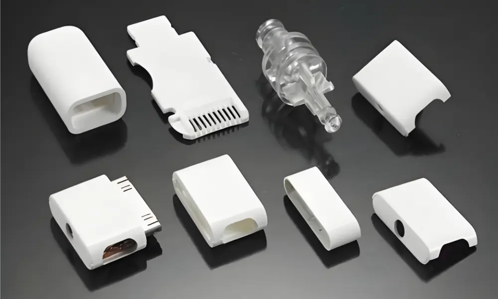
Consumer Electronics
Smartphone connector bodies, smartwatch crown mechanisms, earphone driver housings, and micro-switch actuators demand sub-millimetre feature resolution and optical surface quality on components produced at hundreds of millions of units per year.
LCP dominates connector housing applications because its near-zero shrinkage achieves the ±0.01 mm pin-pocket tolerances required for reliable SMT pick-and-place at 0.3–0.5 mm contact pitch. At these pitches, any positional variation in pin pockets translates directly to assembly yield loss on the PCB.
→ Related: Fecision plastic connector housing injection molding capabilities
Aerospace and Defence
Lightweight sensor housings, micro-actuator components, and connector overmould bodies for avionics applications must meet AS9100 Rev D quality management requirements and pass environmental qualification testing per MIL-STD-810 (shock, vibration, temperature cycling) or DO-160 (airborne equipment environmental test).
Zero-failure tolerance is not a marketing statement in this sector — it is a regulatory and contractual requirement. AS9100 Rev D certified manufacturing with documented process validation and first-article inspection reports (AS9102) is required from approved aerospace suppliers.
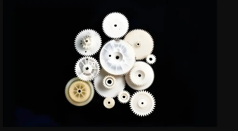
Industrial and Robotics
Precision micro-gears for servo actuators, valve seats for pneumatic micro-valves, and encoder housings for position feedback systems are produced in engineering polymers (POM, PPS, PA66-GF30) that provide the stiffness, dimensional stability, and chemical resistance that industrial service environments demand.
Robotics applications increasingly specify LCP or PPS for arm-end-effector components that must maintain positional accuracy over millions of actuation cycles under thermal and mechanical fatigue loading. The combination of high stiffness and near-zero dimensional drift under cycling is what makes these resins dominant in precision robotics.
Conclusion
Small part injection molding makes reliable production possible for complex miniaturization. Its success depends on the quality of tooling, the level of process control, and the right kind of partner. With all components being in sync, you can create small, high-performance parts that are at the highest quality levels.
Ready to bring your micro-designs to life with unmatched accuracy? Contact Fecision today for rapid DFM, tolerance analysis, and competitive quoting on your small parts injection molding program!


