
Product design illustrations. Final geometry, materials and acceptance criteria are project-specific.
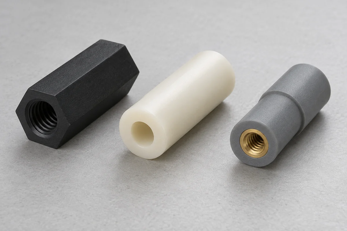
A through-bore spacer and a threaded standoff can establish the same nominal gap while doing different jobs in the fastening system. In one arrangement a screw passes through the support and engages another component. In another the support itself carries a threaded connection. Choosing between them changes assembly access, installation control and what must be validated.
Begin with the joint section rather than a catalog silhouette. Identify where the screw thread engages, which faces carry compression and what prevents rotation during tightening. A hexagonal exterior may provide tool access, but it does not prove thread strength. Likewise, an unthreaded sleeve does not eliminate the need to evaluate the compression it experiences.
Separate the spacing function from the fastening function
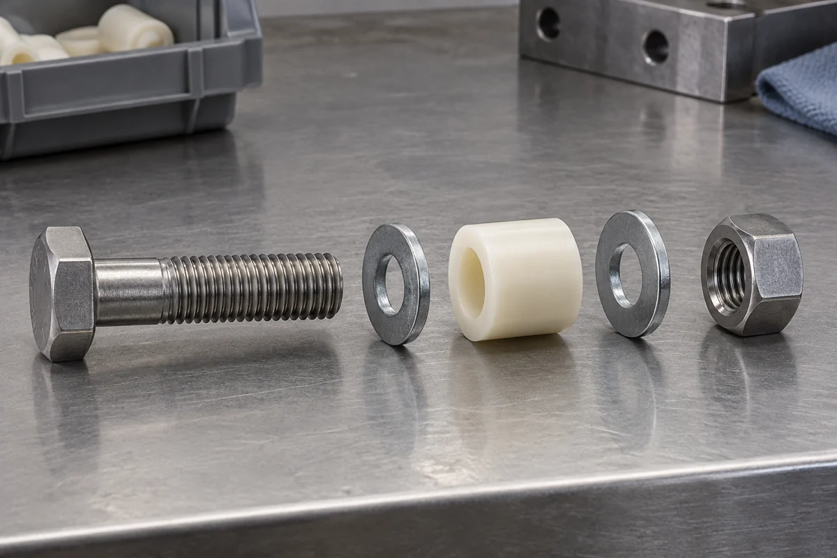
A plain sleeve can provide a controlled distance while a metal screw and a separate threaded component complete the joint. This separation may simplify the spacer geometry, but it requires access to the other side or an appropriate receiving feature. Consider how the assembly is built, repaired and inspected before deciding that fewer features always mean an easier product.
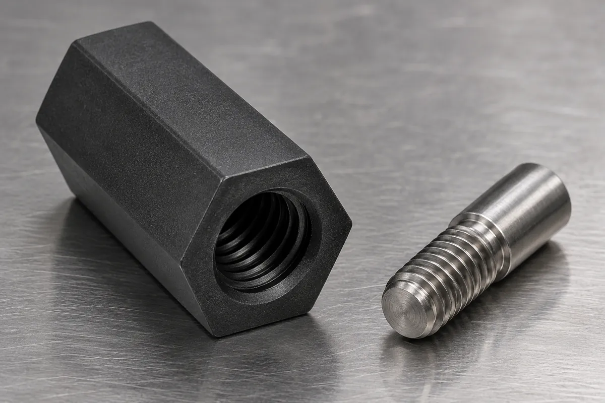
A threaded support combines more functions in one component. It may help where the assembly sequence cannot accommodate a loose nut or long through-screw. In return, the thread, support body and installation method become linked requirements. Drawing approval should cover the complete arrangement rather than only the external height and diameter.
Do not treat all plastic threads as equivalent
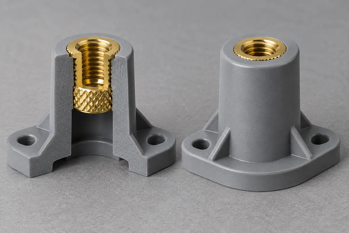
An internal molded thread, a machined thread, a screw forming its own engagement and a metal insert are distinct constructions. Each creates a different manufacturing and assembly sequence. Ask which one is being quoted and whether insertion or secondary work is included. A material family name alone cannot establish the allowable installation torque or reuse cycle.
The legacy DuPont engineering-polymer design manual distinguishes thread-forming and thread-cutting approaches and relates fastening choices to material behavior. Treat it as background, not a current approval for a specific fastener. Use the selected fastener supplier's guidance and current resin information for the actual design.
Reinforcement, moisture condition and geometry can affect how a fastening feature behaves. This is especially relevant if a design changes from an unfilled resin to a glass-filled one. Revalidate the selected connection instead of assuming a material with a higher stiffness automatically tolerates the same installation process.
Define engagement and installation together
Specify the screw type, engagement length, seating arrangement and assembly access. A drawing of the standoff alone may not show whether the screw bottoms out before the joint is clamped. Resolve that with the complete dimensional chain, including counterpart thicknesses and any washers or inserts that occupy the available space.
Installation torque is a process setting, not a direct measurement of retained clamp force. If the application depends on preload, decide how that condition will be evaluated. If it depends primarily on reliable retention and spacing, describe the corresponding acceptance checks. Avoid assigning an impressive torque value without a defined failure mode or test method.
Consider maintenance and electrical separation
Repeated disassembly may influence the preferred connection, but the required number of service cycles must come from the product use. A one-time laboratory assembly cannot establish repeated-service capability. Define how the fastener will be removed and reinstalled, what constitutes damage and whether the support is intended to be replaced during maintenance.
If electrical separation is part of the requirement, review the actual metal path through the joint. A plastic exterior surrounding a metal insert is not automatically equivalent to an all-polymer connection. Clearance, creepage and insulation requirements belong to the complete equipment design; this component description does not confer an electrical safety rating.
Compare quotes on the approved construction
Include insert supply, installation, thread checking and any secondary operations in the purchasing scope. Ask which dimensions are inspected before and after those operations. If a supplier proposes a different construction, review the effect on the assembly rather than accepting it as a price-only substitution.
For an unthreaded solution, focus on bearing-face height, bore clearance and the installed load path. For a threaded solution, add the connection-specific checks. The height-tolerance guide and creep and preload guide help keep the spacing and fastening questions distinct while evaluating them in the same assembly.
A clear RFQ includes the complete joint section, counterpart revisions, fastening method and intended service access. State whether the support is a custom molded component or a standard item being compared against one. With that boundary established, FECISION can review the molding and sample scope without implying that all threaded supports share one capability.
Discuss your custom spacer
Explore our custom injection-molded plastic spacers and standoffs. Send the drawing revision, mating components, material requirements and expected quantities. FECISION can review the molding and sample-approval scope; application ratings and final acceptance must follow the agreed project requirements.