
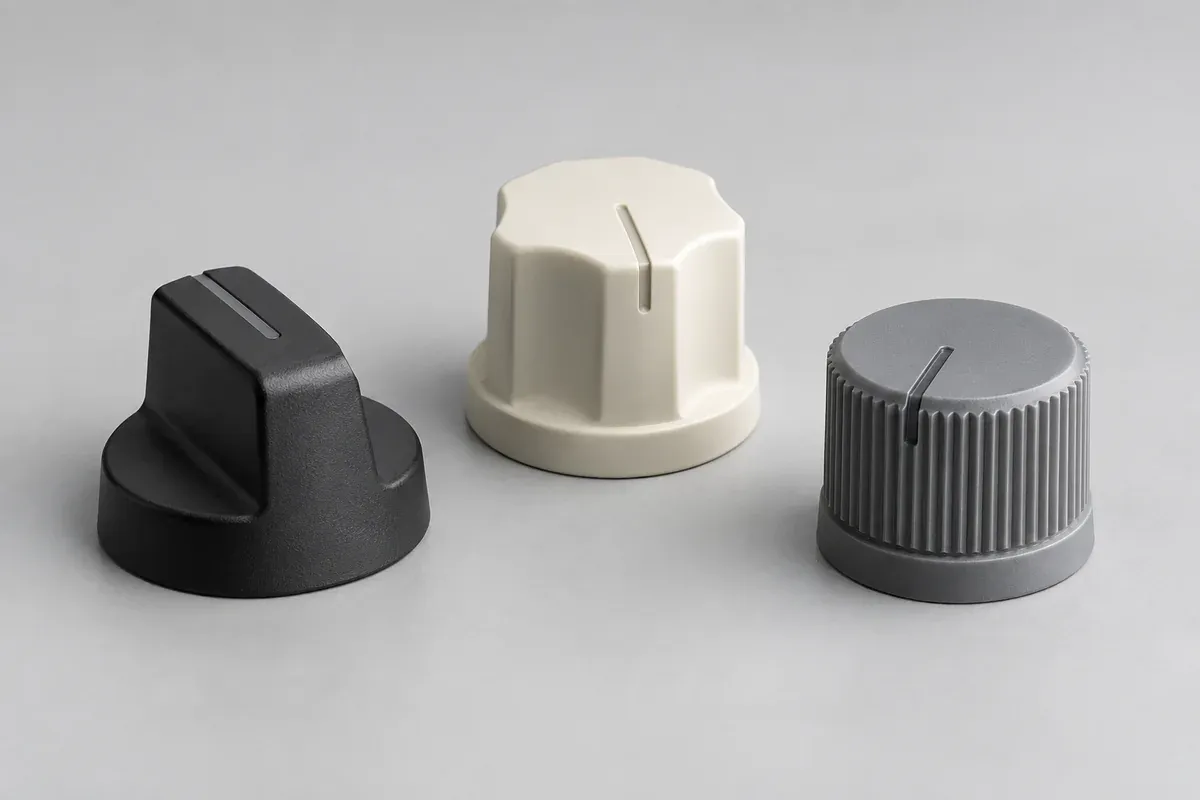
Product design illustrations. Final geometry, materials and acceptance criteria are project-specific.
An index line on a control knob is a functional reference when it tells the user where the control is set. Its appearance matters, but so does its angular relationship to the shaft and panel. Treating the line as decoration can leave an otherwise well-molded knob pointing at the wrong position.
Start with the complete visual system: knob, shaft, panel scale or reference, viewing direction and operating range. Then define which features are molded and which, if any, are applied afterward. This separates geometry decisions from marking-process and assembly decisions.
Connect the index to a controlled reference
Identify the feature that fixes the knob's angular orientation. For a D-shaped interface, relate the index to the specified flat. For an adjustable round-shaft arrangement, define how assembly establishes the index position. A circular outside diameter cannot provide an angular datum by itself.
Show the relationship on the drawing rather than relying on a product photograph. Include the intended assembled state of the control and any required panel reference. A mark can be correctly located on the knob yet appear wrong because the control body was installed in a different orientation.
The shaft-fit guide explains the underlying interface. Keep that definition consistent with the cosmetic model so a late appearance change does not rotate or otherwise alter the functional reference.
Choose a marking method for a defined purpose
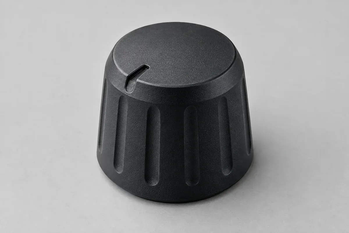
A molded notch or raised feature is part of the tool geometry. A printed, filled or otherwise secondary mark adds a process and its own acceptance conditions. Decide whether contrast, tactile location, durability or a combination of these is required.
Ask which secondary methods are available for the selected resin and surface. Do not assume that a marking process suitable for one grade or color will deliver the same result on another. Evaluate representative samples when appearance or persistence is important.
Specify what the mark must communicate and the conditions in which it will be viewed. If it forms part of a safety-related interface, its requirements need review by the responsible product designer. A generic knob illustration does not establish legibility or compliance.
Make texture zones deliberate
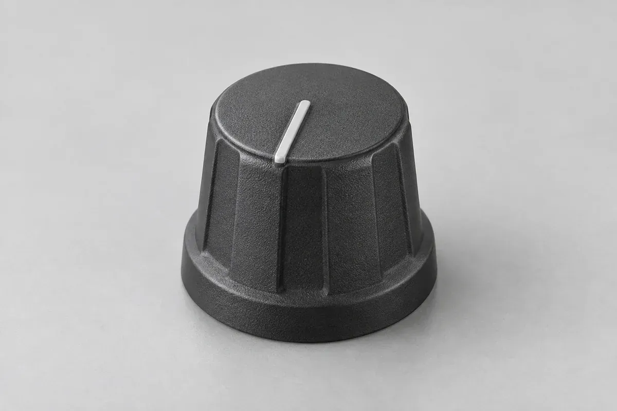
Separate the grip rim, visible top and any hidden assembly surfaces. They may need different finishes. A texture chosen for the outer grip should not automatically extend into a bore or seating face where it could change fit or inspection.
Discuss texture with the mold maker while draft and release are being reviewed. The tool's surface treatment is not an independent final decoration. It interacts with geometry and the permitted appearance of the molded part.
Use an approved physical reference where a precise cosmetic match matters. A screen rendering is useful for layout, but lighting and display settings can make color and gloss comparisons unreliable. Record the viewing conditions used for sample approval.
Place molding witnesses around the functional surfaces
Identify the allowed gate, parting-line and ejection regions. A gate remnant on the grip or an ejection mark across an index can create a functional or cosmetic issue. Mark prohibited areas and discuss alternatives before tooling is committed.
A hidden area is not automatically unrestricted. The underside may contain a critical seating face, insert reference or shaft interface. Tooling decisions should respect those functions even when the surface is not visible after assembly.
Review the proposed witness locations alongside any secondary marking fixture. The fixture should locate from stable, agreed features rather than a variable remnant. This helps keep marking position connected to the same reference system used by the molded component.
Approve appearance and alignment separately
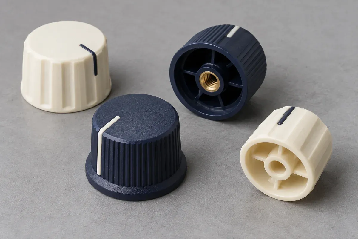
Inspect the mark's position on the component, then assess its indication on the representative assembly. Record knob, shaft and panel revisions. A successful visual check on one loose part should not replace the assembled angular relationship review.
If use or cleaning can affect the mark, define the required evaluation before production. Describe the exposure, observation method and acceptance criteria rather than promising that an unspecified marking is permanent. Retain sample identity through any comparison.
Include the chosen finish and marking scope in the quotation, with any unresolved choices clearly identified. Pair it with the functional acceptance plan so the released knob has both a controlled appearance and an approved mechanical interface.
Turn the review into a defined molding scope
Explore our custom injection-molded control knobs and the related illustrative engineering study. Send the drawing revision, counterpart details, intended use and the decisions still open. Development samples and production approval should have separate, agreed deliverables.