
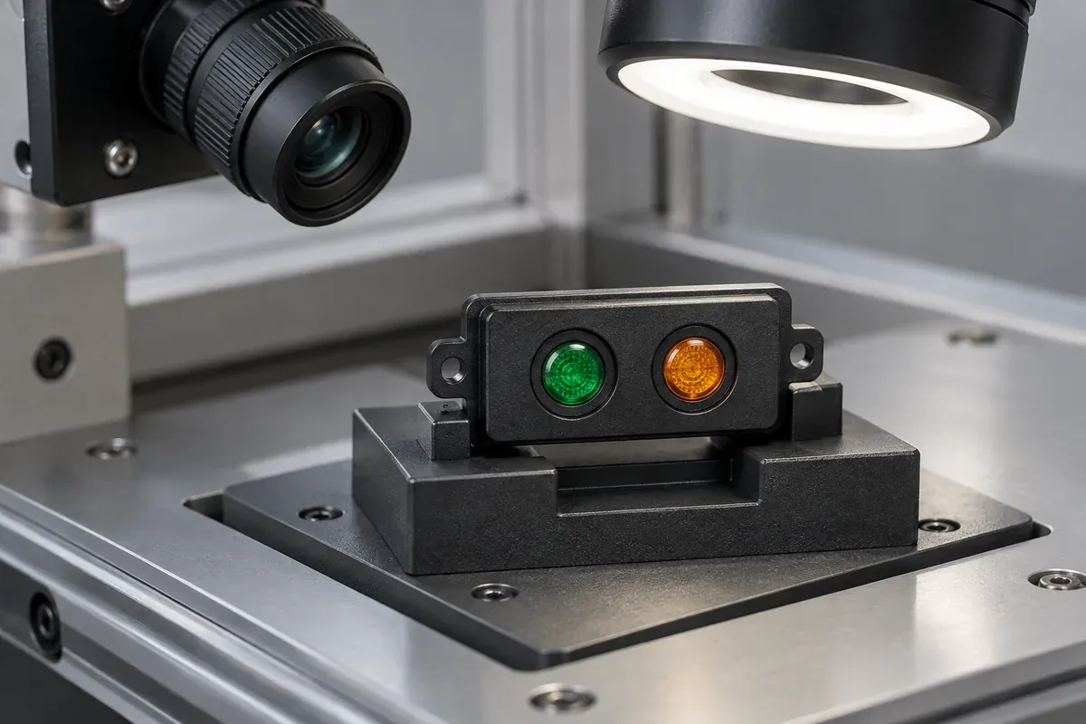
Product design illustrations. Final geometry, materials and acceptance criteria are project-specific.
“Bright and uniform” sounds clear until two reviewers examine the same light pipe on different benches. One sees a strong indicator; the other sees a central hot spot and an unwanted glow in the neighboring window. Both may be accurately describing different conditions. Acceptance begins with the assembly and observation method, not an attractive photograph.
This guide sets out how to prepare an application-specific sample review. It does not assign a universal brightness target, minimum uniformity ratio or pass rate. Those criteria must follow the indicator's intended use and the method chosen to evaluate it.
Freeze the source and assembly configuration
Identify the LED part and relevant source characteristics, drive settings, board revision, light-pipe revision and material grade. Include the carrier, panel, mask and any lens or diffuser used in the final arrangement. Record whether the samples are molded from the proposed production material or are development substitutes.
Keep the mounting relationship controlled. A guide resting freely above an LED is not equivalent to one retained against a panel with a defined entrance gap. Before blaming the clear material, check whether the fixture repeats the board-to-guide position and whether any contact is changing the path.
If temperature stabilization matters for the chosen source and measurement, define it in the procedure. “Wait until it looks steady” is difficult to reproduce. The necessary stabilization condition should be set by the test owner for the actual hardware rather than copied from an unrelated LED application.
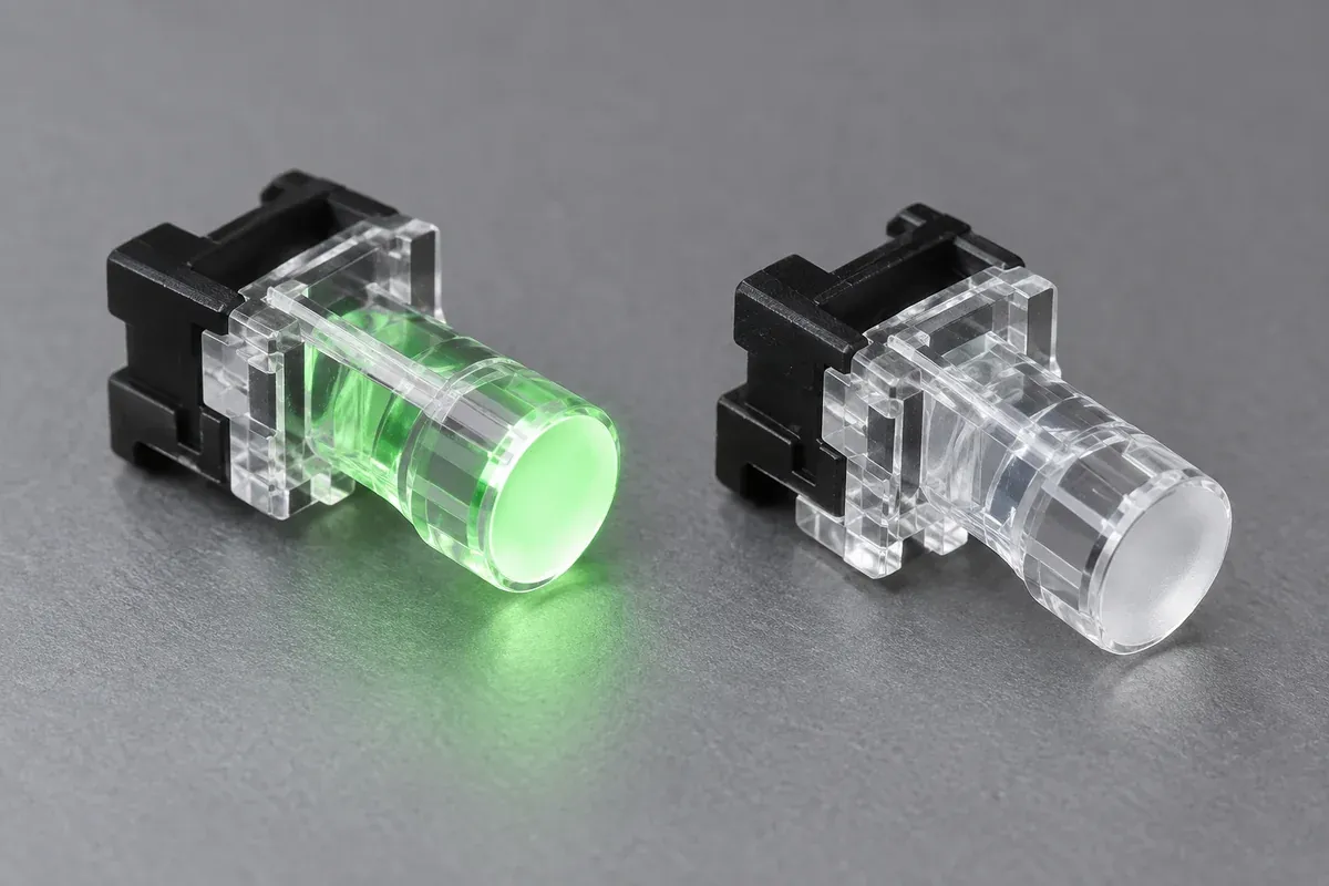
Define what the observer is judging
Set viewing distance, direction, permitted angle range, ambient illumination and background. A status light used from an oblique position has a different requirement from one viewed only head-on. Decide whether the user must recognize an active state, distinguish colors, read an illuminated symbol or compare neighboring indicators.
VCC describes a hotspot as a locally brighter area. That terminology helps describe a symptom, but it does not provide an acceptance boundary. State which visible region is evaluated, what variation is objectionable and whether a controlled reference sample or a numerical method governs the decision.
For a numerical method, name the measured quantity, instrument, geometry and calculation. Do not substitute a convenient sensor reading for an undefined concept of brightness. If a uniformity ratio is used, specify where readings are taken and how the ratio is calculated; different sampling areas can produce different answers from the same exit.
| Item | Record | Why it matters |
|---|---|---|
| Source | LED identity, drive and stabilization condition. | A source change can look like a molding change. |
| Assembly | Guide, panel, carrier and locating references. | Position and masks affect the visible result. |
| Observation | Distance, angle, ambient light and background. | Appearance is not independent of viewing conditions. |
| Decision | Visual reference or instrument method and approved limits. | A descriptive adjective alone does not resolve a disagreement. |
Evaluate individual and combined indicator states
Start with all relevant indicators off to understand ambient effects. Then operate one at a time and examine both its intended window and the neighboring windows. Add simultaneous states where the product uses them. Record the state for every observation rather than collecting unlabeled photographs.
This sequence separates low useful output from crosstalk. A very bright guide may still fail if its neighbor appears active. Likewise, a well-isolated guide can be too difficult to see from the required angle. Keep the two decisions separate so that a change improving one does not conceal a regression in the other.
See our isolation review for possible unwanted routes. If the result changes when the board moves, return to the entrance gap and alignment relationship before changing the material specification.
Use photographs as controlled records
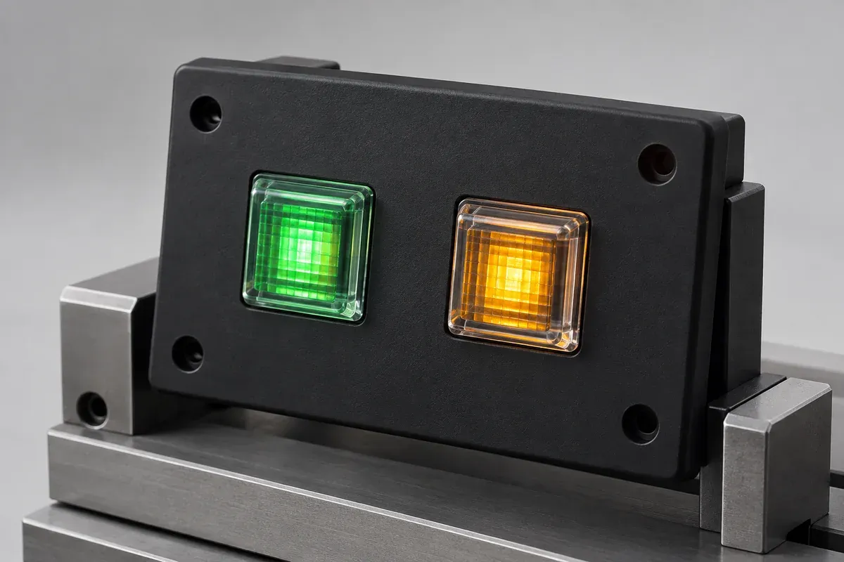
A camera can be helpful for documenting a defect location or comparing a visible pattern. Automatic exposure, white balance, focus and processing can also change the apparent result. If photographs form part of the acceptance record, agree their setup and retain the underlying files with the relevant sample identity.
Do not infer absolute optical performance from an uncalibrated image. A rendered illustration is suitable for explaining a proposed design; it is not sample evidence. Keep product-design visuals distinguishable from photographs collected during an actual approved evaluation.
Handle samples consistently. Fingerprints, scratches and cleaning residue can influence an inspection, while polishing or wiping one sample differently creates a new condition. Define permissible cleaning and surface protection, and record any sample that is modified during investigation.
Release a configuration with its evidence
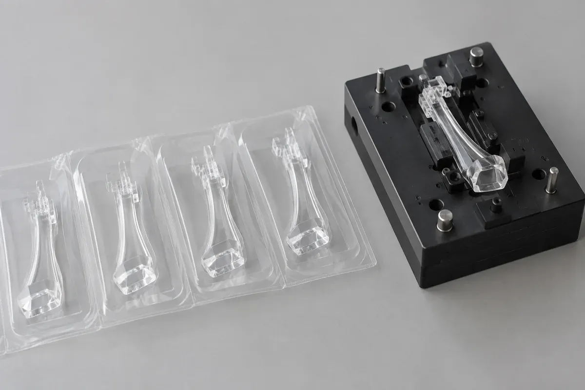
Agree sample coverage with the development and production teams, including cavities and conditions relevant to the decision. Retain links between drawing revision, resin, molding run, assembly parts and observations. A selected attractive specimen should not silently represent a different cavity or a later material substitution.
The useful acceptance package states what was evaluated, how, against which criteria and with what unresolved limitations. If the design changes, decide which checks must be repeated. That provides a defensible route from a sample review to production approval without inventing numerical promises before the application is understood.
Turn the review into a defined molding scope
Explore our custom injection-molded LED light pipes and the related illustrative engineering study. Send the drawing revision, counterpart details, intended use and the decisions still open. Development samples and production approval should have separate, agreed deliverables.