
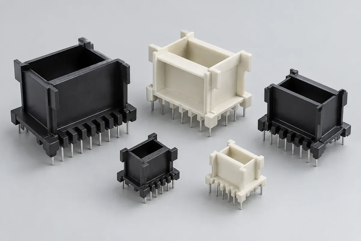
Product design illustrations. Final geometry, materials and acceptance criteria are project-specific.
A transformer bobbin is not simply a spool of the right outside size. Its winding space, core passage, flanges and terminal arrangement connect several manufacturing operations. An apparently small change to one feature can prevent the winding machine, core or circuit board from accepting the component.
This guide concerns custom molded plastic coil formers for electrical assemblies, not sewing bobbins or finished transformers. Start with the components and processes that surround the bobbin. That gives a molding supplier a usable interface specification instead of an isolated shape to price.
Describe the winding and core spaces separately
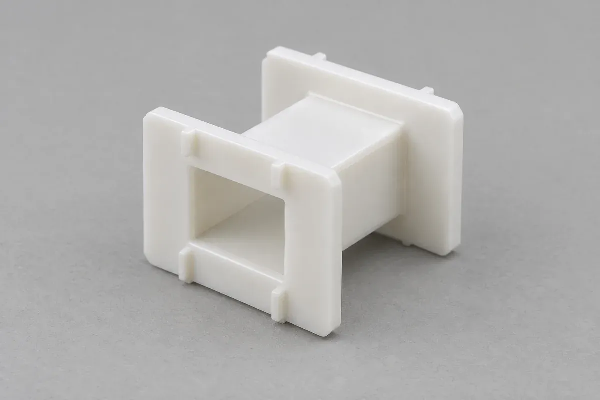
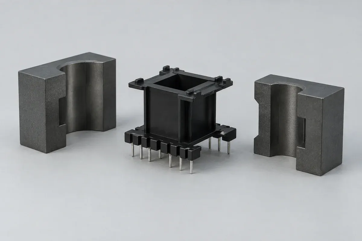
The barrel supports the winding, while the passage through it accommodates the selected core geometry. Define both using controlled drawings. A core designation is useful background, but the actual mating dimensions and permitted assembly freedom still need to be available to the team.
The usable winding envelope also depends on flange geometry, lead routing and the intended insulation arrangement. Do not equate the empty space shown in CAD with approved winding capacity. The electrical designer and winding process owner must establish what can occupy that space.
A supplier such as Lodestone Pacific distinguishes standard and custom bobbins. That is a useful procurement distinction: if an existing former satisfies all interfaces, custom tooling needs a clear reason, such as a different terminal layout or constrained assembly envelope.
Follow the wire from entry to termination
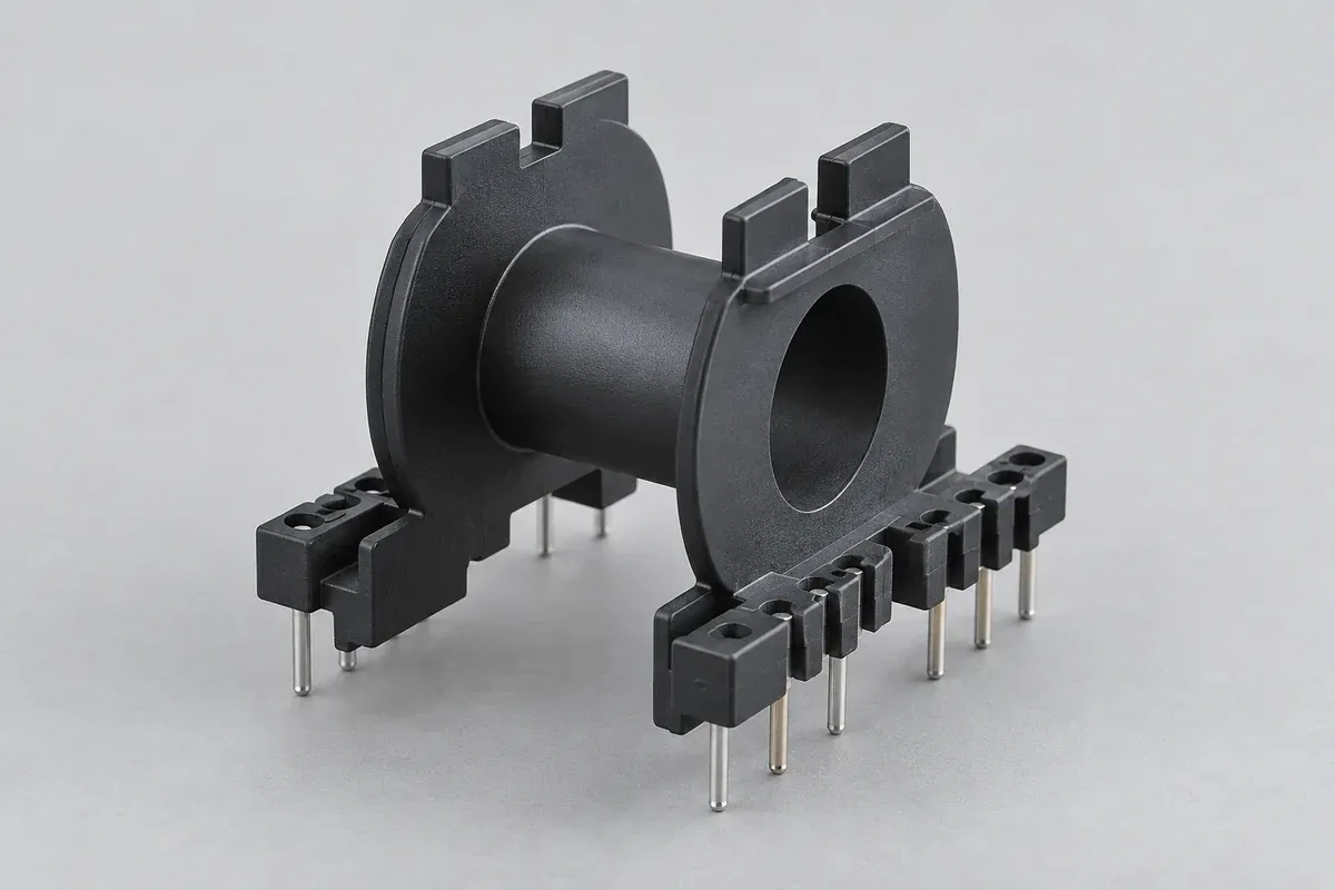
Show where the winding begins and ends, how leads cross or pass through the flange, and which surfaces the wire can contact. Local edge condition matters because a nominal slot width says little about a sharp molding witness at its entrance.
Identify the terminal system. Molded-in pins, subsequently inserted pins and separate termination hardware create different delivery and inspection scopes. If terminals are excluded from the molding order, specify the receiving holes and the condition in which the empty bobbin will be supplied.
The pin assembly comparison explains why these alternatives need distinct quotation assumptions. A supplier cannot reasonably compare prices if one proposal includes terminal procurement and installation while another covers plastic alone.
Agree what locates the component downstream
Ask the winding team which features seat in the nest and which establish rotation or axial position. Keep gate remnants and parting lines away from those references where the design requires it. A convenient tool location is not automatically a suitable assembly datum.
Next examine core insertion and board placement. The relevant references may differ between operations. Document their relationship so that a fixture does not force the part into a position that disguises a molded feature error.
Include the assembled envelope of pins, wire exits and any intended retainers. Measuring only the bare plastic can miss interference that appears after a later operation. Conversely, a completed assembly check does not replace inspection of an inaccessible internal feature.
Put material requirements in an application brief
Send the proposed exact grade, relevant temperature exposure, winding and termination processes, and required material records. A polymer family name is not enough to establish suitability for an electrical application. Grade, reinforcement, color and documented test conditions can all matter.
If material selection is open, identify the decision owner and the required evidence. Request a candidate review rather than allowing an unapproved substitution to become the quotation baseline. The bobbin material guide outlines a comparison structure.
Keep finished-device qualification separate from molding capability. A recognized material does not make a complete transformer certified, nor does the shape of a flange establish compliant insulation spacing. Those evaluations belong to the responsible electrical engineering process.
Request comparable tooling and part quotations
Provide the drawing revision, CAD, sample quantity, repeat demand, packing needs and destination. State whether pins, secondary operations and inspection reports are included. Separate the initial tool and sampling scope from recurring production pricing so commercial differences remain visible.
Before release, agree a trial sequence that checks the empty component, terminal configuration and representative downstream assembly. Capture unresolved assumptions in the proposal. The objective is an approved interface package, not a low unit price based on an incomplete description.
Turn the review into a defined molding scope
Explore our custom injection-molded coil bobbins and the related illustrative engineering study. Send the drawing revision, counterpart details, intended use and the decisions still open. Development samples and production approval should have separate, agreed deliverables.