
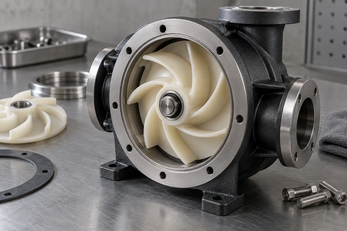
Product design illustrations. Final geometry, materials and acceptance criteria are project-specific.
Thin impeller blades create a manufacturing challenge because they connect a delicate flow geometry to a comparatively substantial hub. A blade can appear complete and still have distortion that matters to the pump assembly. The review must preserve the hydraulic intent while identifying where molding and inspection need additional control.
Start with the surfaces and edges that the pump designer considers critical. Identify permitted changes separately from fixed geometry. This prevents a well-intended manufacturing adjustment from changing blade angle, passage area or clearance without the system designer understanding the consequence.
Review section transitions and filling
Abrupt changes between blade and hub sections deserve attention because the regions fill and cool differently. A thicker junction may also be the location of a structural or hydraulic requirement. Review the transition rather than automatically thickening every blade or removing material from the hub.
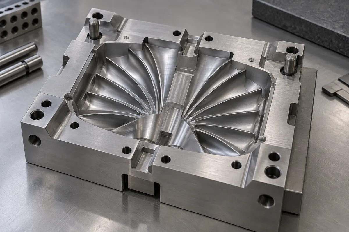
Gate location influences the path by which material reaches the blade features. Ask where flows meet, which regions are difficult to fill and how the proposed process handles them. A fill simulation can support this discussion, but its assumptions and material data should be stated.
General wall-thickness guidance for injection molding helps explain why section consistency matters. An impeller still requires a geometry-specific review, particularly where the hydraulic design intentionally uses changing blade thickness.
Separate material orientation from nominal shape
With reinforced polymers, local flow can influence fiber orientation and directional behavior. This can affect how the part changes during cooling or later exposure. Do not assume that one uniform shrinkage allowance will describe every blade and hub feature equally well.
Examine the cooling and ejection plan. A part removed while vulnerable to deformation may change shape under an unbalanced release load. The tool must support the intended geometry without leaving unacceptable marks or making the molded component difficult to remove consistently.
Review weld regions against structural and operating requirements. Their importance depends on the actual material, geometry and loading. Avoid declaring every visible line harmless or every flow meeting point unacceptable without relating it to the component's function and the available test evidence.
Measure the shape that matters
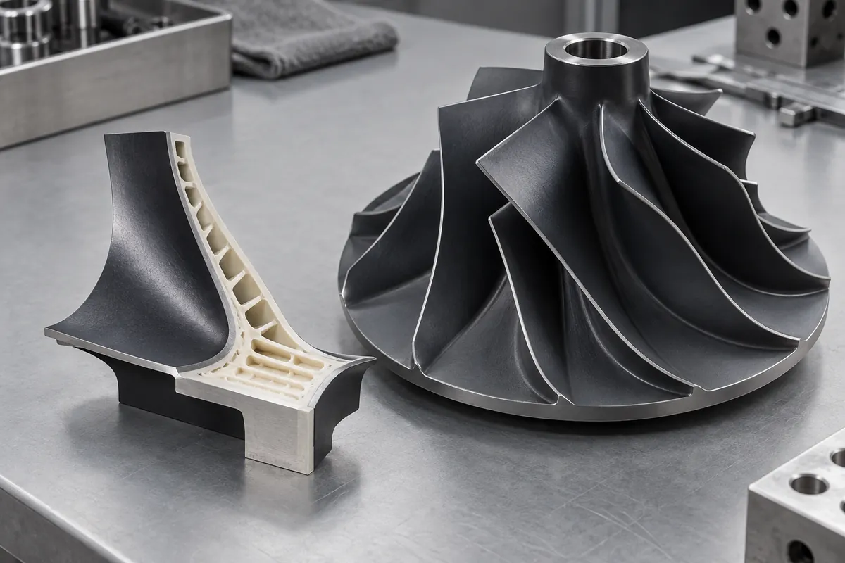
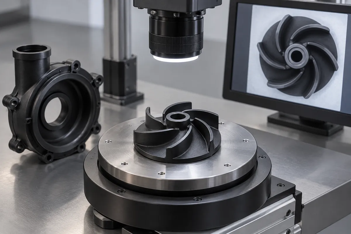
Define blade inspection references that relate to the shaft axis and assembled clearances. Measuring only outside diameter can miss changes in local blade angle or passage shape. Decide which features need dimensional measurement and which can be evaluated through an agreed profile comparison.
Specify the sample condition and time after molding where those affect the result. A warm freshly released component and a stabilized component may not present the same geometry. If fluid conditioning is relevant, keep that later evaluation distinct from initial molding inspection.
Use cavity-level identification when comparing samples. An average across all cavities can hide a consistent problem in one region of the tool. Relating deviations to cavity and process history makes corrective work more focused than repeatedly adjusting a global dimension.
A useful development comparison preserves both an uncorrected sample and the proposed corrected geometry in the record. This helps the pump designer assess whether the manufacturing adjustment changed the intended flow surface. It also avoids losing the original reference when several tooling iterations produce visually similar but dimensionally different blades.
Make changes through a controlled development loop
When a trial shows warpage, record the direction, magnitude and repeatability before changing geometry. Consider tool, process and material factors together, while changing variables deliberately enough to understand their effects. A visually improved sample does not by itself establish a stable production process.
Check any proposed correction against the shaft interface and housing clearance. A change that improves blade shape may alter the hub or another critical feature. Approval should cover the complete component rather than one isolated measurement.
Retain the final drawing, material, tool revision and inspection method as one release baseline. If the hydraulic surfaces cannot be produced within the required limits, resolve the design or process route explicitly rather than accepting an undocumented compromise because the part looks close to the model.
Discuss the component and its acceptance requirements
Explore our custom plastic impellers and the related project case study. Send the current drawing, mating-part details, operating conditions and required quantities. We can review tooling, molding and inspection as a defined supply scope, with development samples and production approval kept separate.