
Product design illustrations. Final geometry, materials and acceptance criteria are project-specific.
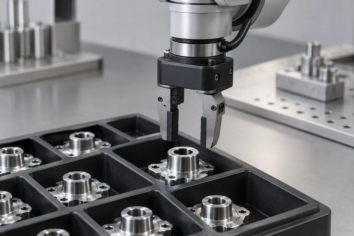
A robot can repeat its programmed motion accurately and still miss a component if the tray does not present that component consistently. Tray location, pocket clearance, part variation and gripper approach all contribute to the pickup condition. Designing the carrier independently from the automation leaves these interactions to be discovered during commissioning.
Begin with the loading and unloading sequence. Identify which device locates the tray, which feature locates the component and how the robot determines the pickup position. A fixed-motion system, a vision-guided system and a compliant gripper can tolerate different kinds of variation, so the tray specification should reflect the actual method.
Establish a usable datum scheme
Choose stable external tray references that the handling fixture can access without contacting the payload. A large flexible rim may not be a suitable precision datum unless it is supported predictably. Locate the tray in a way that does not distort the pockets or depend on an uncontrolled clamping force.
Relate pocket positions to those external references. Measuring each pocket against a different local edge can produce an apparently acceptable tray whose global pickup pattern is wrong. The inspection drawing should reproduce the functional locating scheme used by the automation.
Custom injection-molded handling trays are an established packaging category. Their automation suitability still depends on the actual fixture and motion plan, rather than the fact that the pockets were produced by injection molding.
Leave space for the end effector
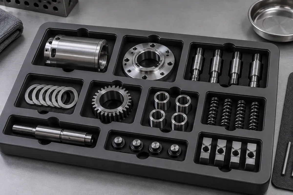
Model the complete gripper envelope during approach, closure and withdrawal. Parallel jaws need access beside the component, while suction tooling needs a usable contact surface and a reliable release from the pocket. Nearby walls and neighboring parts must remain clear throughout the motion.
Consider what happens if the component is seated at a permitted extreme of its clearance. A gripper that works only at nominal position may contact the tray or push the part sideways. Review tolerance-limit positions and any orientation ambiguity before freezing the pocket geometry.
Provide a deliberate way to detect an empty pocket or an incorrectly seated component. This may be handled by sensors, vision or the process sequence rather than by the tray alone. The carrier should support that detection without adding unnecessary reflective surfaces or obscured regions.
Control presentation and condition
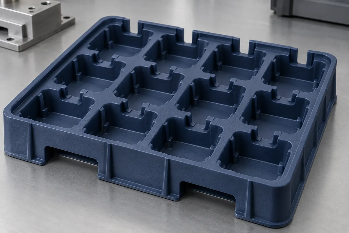
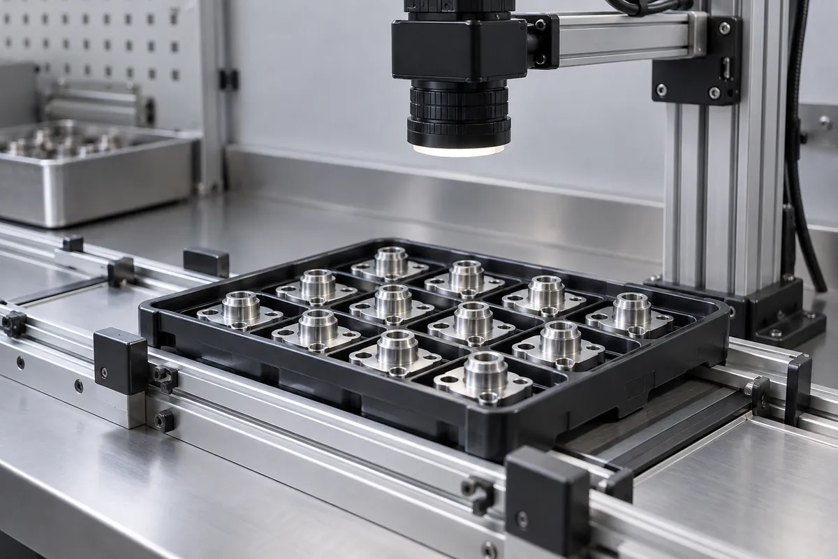
For vision-guided handling, evaluate surface texture, color, background and illumination with the actual system. A glossy pocket can introduce reflections that change as the tray moves. Do not assume a material-color change is purely cosmetic when the detection algorithm uses that contrast.
Review flatness and loaded support. A tray held at its corners may sag differently from one on continuous rails. That change can alter pickup height across the array. If the system compensates for height variation, define its usable range and verify that the molded carrier remains within it.
Include cleaning, wear and component debris in the operating review. Small particles can change seating, and damaged locating features can shift the whole array. Establish a practical incoming or line-side inspection so degraded carriers are removed before they create repeated automation faults.
Validate the cycle, not a single successful pick
Test representative pockets, cavities, component tolerances and loading conditions. Record failures by type: missed detection, poor grip, collision, double pick or incomplete release. A single total success percentage can hide a repeatable problem at one location or under one operating condition.
Include transfer into and out of the station, plus any de-nesting operation. The tray must arrive in the intended orientation and condition before the robot can use it. Validate the practical recovery sequence after an interrupted cycle as well as normal operation.
Release the carrier drawing together with the approved fixture references, end-effector envelope and inspection method. Later changes to the component, tray material or pocket geometry should trigger review against those interfaces. That keeps repeat production aligned with the automation configuration that was actually tested.
Discuss the component and its acceptance requirements
Explore our custom component trays and the related project case study. Send the current drawing, mating-part details, operating conditions and required quantities. We can review tooling, molding and inspection as a defined supply scope, with development samples and production approval kept separate.