
Custom molded parts · Made to your design
Custom Injection-Molded Component Trays
Protect and present the component through its complete handling cycle.
We review custom rigid trays with the carried component, rack or conveyor and removal method. Pockets, support ribs, locating features and stacking interfaces are developed around defined production needs. Electrical-protection requirements require their own compound and finished-part evidence.
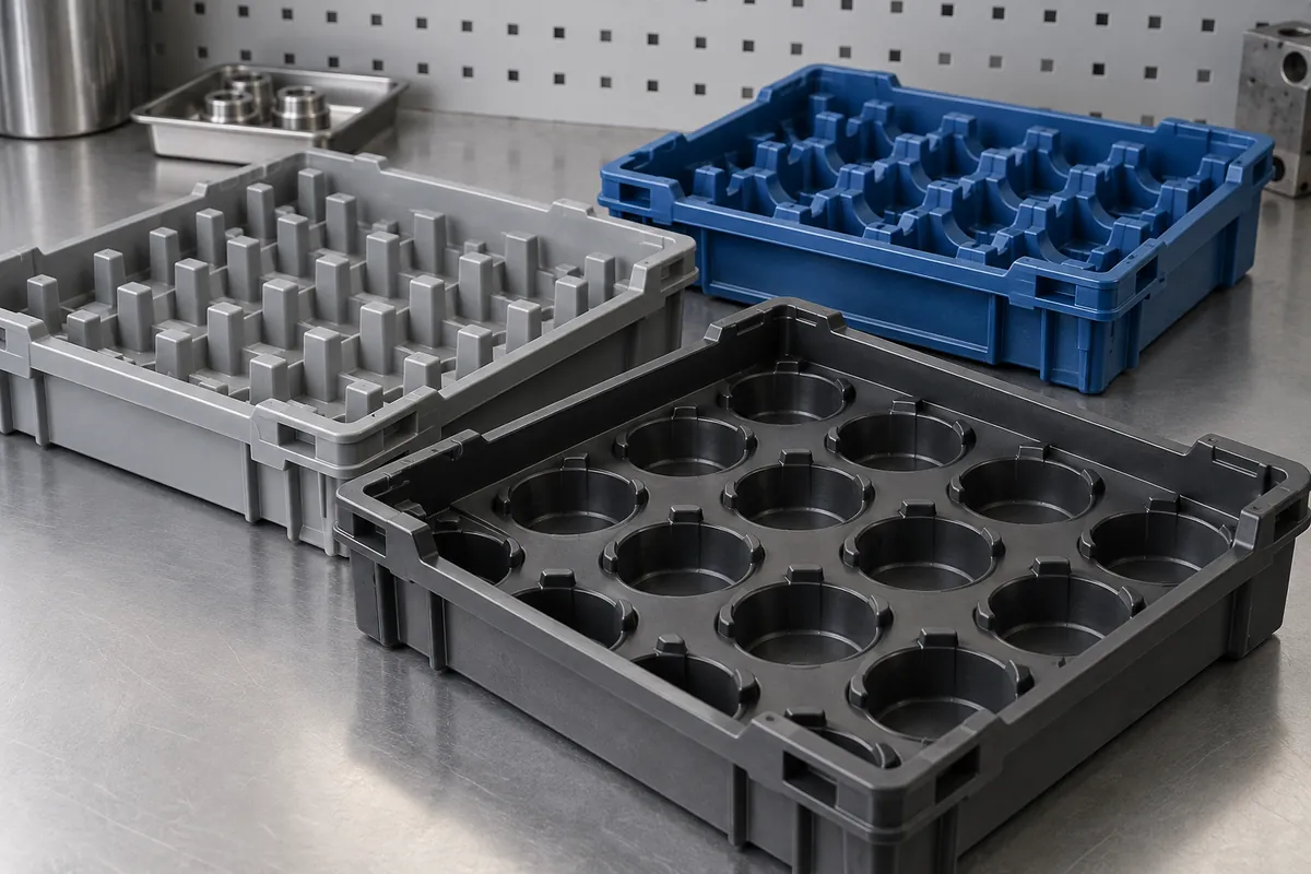
Product details
Component Trays: product details
Product design illustrations showing component features and assembly relationships. The final geometry is made to your approved drawing.
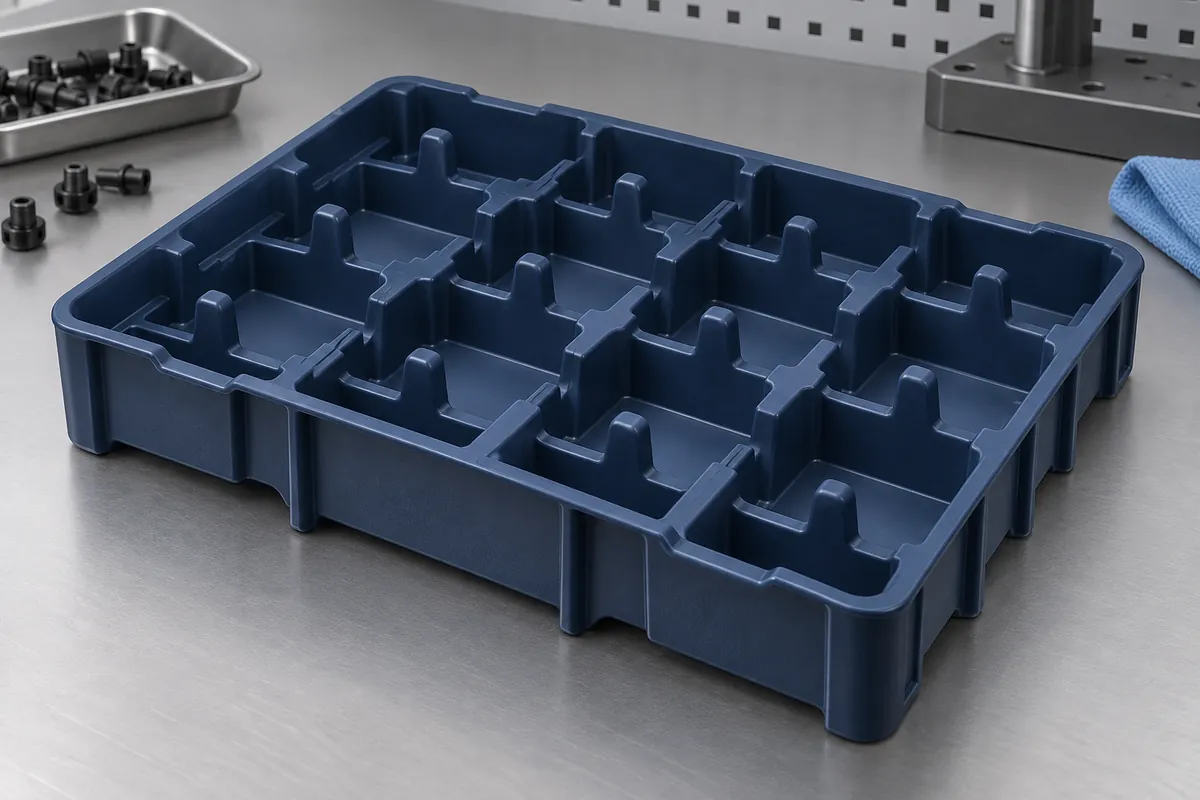
Pocket support
Locate the component on approved contact regions.
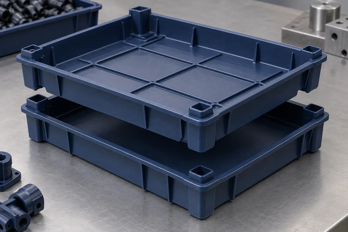
Stacking rim
Transfer stack load through defined supports, not the payload.
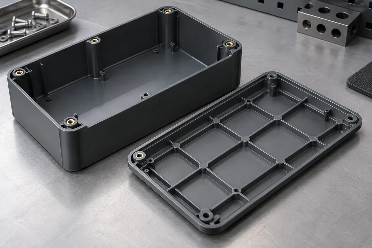
Rib structure
Review thickness transitions, flatness and support spacing.
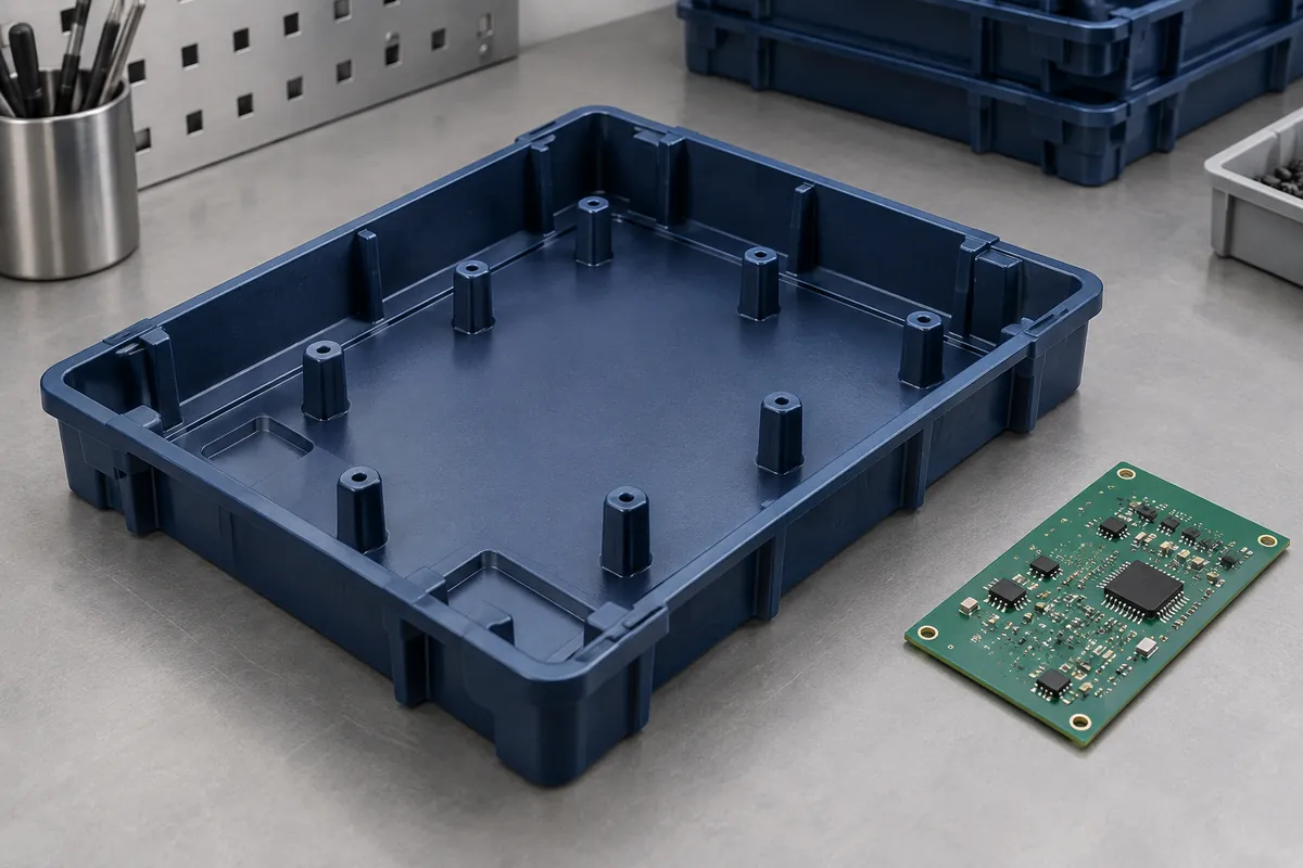
Locating bosses
Relate component positions to the tray fixture datums.
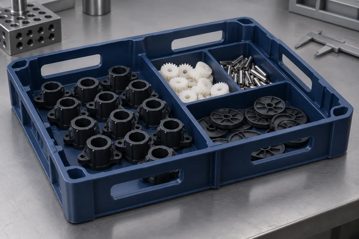
Removal access
Allow clearance for the complete gripper approach and extraction.
Illustrative configurations. Final specifications follow your approved drawings.
Application fit
A custom component with a defined purpose
Protect and present the component through its complete handling cycle.
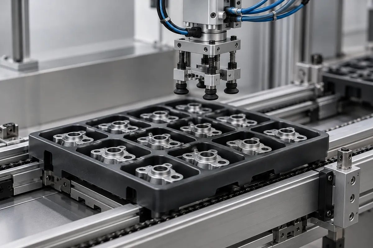
Production handling
Reusable carriers for controlled component positioning between operations. Identify permitted contact surfaces and vulnerable features.
Automated presentation
Pocket arrays, gripper access and external references designed with the handling fixture and sensor arrangement.
Stacked transport
Loaded stack interfaces and empty nesting reviewed separately, including bottom support and separation access.
Quote-ready inputs
What to send for a meaningful quotation
Use the same drawing and requirements for every proposal. Mark open decisions explicitly so that a low price does not conceal a different deliverable.
| Area | Please provide | Review before release |
|---|---|---|
| Project definition | Current CAD, drawing revision, mating components and quantities. | Mark fixed interfaces and open design decisions before comparing quotations. |
| Payload | Component CAD, weight, contact restrictions and variation. | Protect the part without trapping it in the pocket. |
| Handling | Stack load, rack supports, conveyor and gripper envelope. | Check the loaded configuration rather than an empty bench sample. |
| Electrical requirements | Required protective function, method, conditioning and resistance window. | Black color and conductive filler alone do not establish ESD certification. |
| Supply and release | Trial, first-order and repeat quantities, packing and report needs. | Agree tooling scope, approval hold points and change control. |
From drawing to approval
From the assembly requirement to production approval
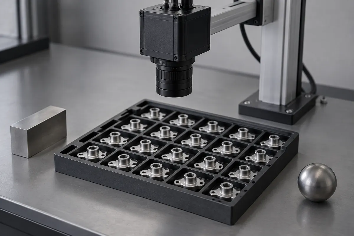
Align the scope
Align tray and payload revisions, review pocket and rib geometry, trial the molding process, and validate loaded handling and any electrical requirements.
Review the tool and material
Confirm the exact compound, molding route and any secondary operations. Resolve proposed changes against the functional drawing before tooling release.
Evaluate identified samples
Record cavity and lot identity with dimensional and agreed functional observations. Keep incomplete validation separate from completed acceptance.
Release the approved configuration
Retain the drawing, material, process route and inspection method. Review later changes against the configuration that was actually approved.
Practical engineering and buying guides
Decisions to make before production
- Injection-Molded vs Thermoformed Trays for Reusable HandlingCompare injection-molded and thermoformed component trays for repeated handling, locating features, stacking, cleaning and total supply scope.
- PP vs HDPE for Injection-Molded Component TraysCompare PP and HDPE for molded component trays using stiffness, impact, cleaning exposure, additives and loaded-part validation rather than resin labels alone.
- Tray Pocket Design: Protect Parts Without Trapping ThemDesign component-tray pockets around support zones, extraction clearance, tolerances, draft and inspection. Protect delicate surfaces without trapping the part.
- Stackable Tray Design: Nesting, De-Nesting and Load PathsDesign stackable and nesting plastic trays with defined load paths, anti-jam features and separation access. Validate loaded stacks and automated de-nesting separately.
- What Makes a Plastic Tray ESD-Safe? Material and EvidenceEvaluate ESD tray claims with the finished compound, resistance method, conditioning and handling function. Distinguish dissipative behavior from shielding and symbols.
- Designing Molded Trays for Robotic Pick-and-PlaceDesign injection-molded trays for robotic handling with controlled datums, gripper access, part orientation, vision conditions and tolerance-aware validation.
Before you request a quote
Can a black tray be advertised as ESD-safe?
Not from color alone. Define the required function and evaluate the exact compound and finished tray under an agreed method.
Can one tray support both stacking and nesting?
Potentially, after reviewing feet, rims, separation and component clearance. The two functions need separate validation.
What makes a tray suitable for robotic picking?
Repeatable datums, component presentation and gripper access are key inputs. Validation must include the actual fixture and motion sequence.
Your next step
Discuss the part with its intended function.
Send the component trays drawing with its mating interfaces and acceptance requirements. We will review the proposed molding scope and identify the information needed for a meaningful quotation.
Explore our injection molding service or review other custom molded applications.