
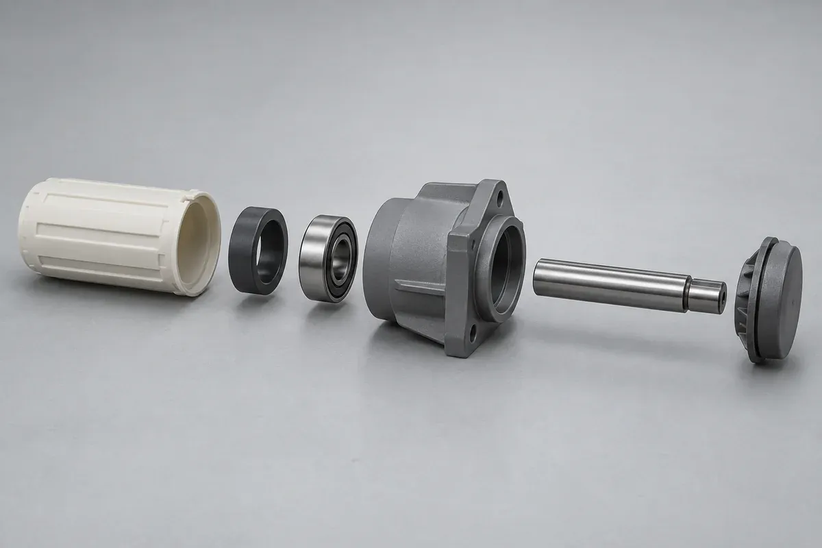
Product design illustrations. Final geometry, materials and acceptance criteria are project-specific.
The loose bushing accepts a gauge pin, but after installation the shaft feels tight. That observation does not necessarily mean the molded bore was wrong. Pressing a polymer sleeve into its housing changes the constraint on the part, so the working bore must be considered in its installed condition.
Begin with the assembly definition rather than immediately enlarging the tool core. The housing bore, sleeve wall, intended interference, lead-in and installation method all participate in the result. A change to the bushing may hide a counterpart problem and create a loose fit when other permitted components are assembled.
Separate three dimensions and two states
Record the shaft outside size, housing bore and bushing geometry. Identify which bushing dimensions apply before installation and which are required after installation. The same drawing should not leave both interpretations plausible.
igus's installation guidance explicitly describes how press fitting participates in the final bearing bore. Its catalogue tolerances apply to its own products and specified housings, not automatically to every custom sleeve. Use that distinction to ask the right question, not to copy a fit class without review.
State the housing material and wall geometry. A rigid metal block and a thin molded bracket do not necessarily respond alike during installation. If the housing deforms, the outcome is a coupled assembly behavior rather than a property of the sleeve alone.
Check the installation path
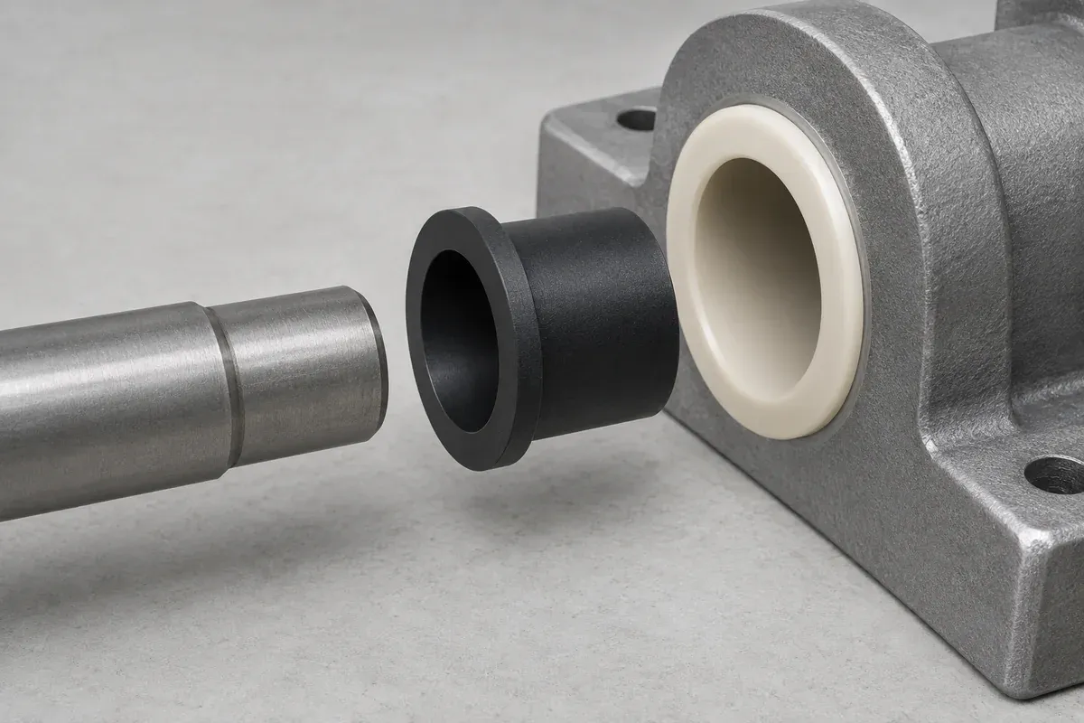
Look for cocking, a damaged entry edge, trapped debris or an unsuitable pressing tool. Define the surface that receives the installation load and the housing support beneath it. Do not push against a thin flange or optical-looking cosmetic face simply because it is accessible.
Confirm the bushing reaches its intended seat. A partially installed sleeve can present a different bore form or leave the shaft engaging an unsupported section. Record insertion depth and seating separately from a single overall force observation.
If lubricant or another assembly aid is permitted, identify it and its amount or method as appropriate. A trial performed with an undocumented lubricant should not become the basis of a dry-assembly production requirement.
Measure the installed bore without forcing the answer
Agree a method suited to the feature and decision. A plug gauge can help establish a defined size check, while dimensional measurement can reveal variation along the bore. Neither should use enough force to reshape a compliant sleeve and then report that reshaped condition as free clearance.
Identify axial locations and orientation if form matters. A single reading at the entrance may miss a tighter region farther inside. Likewise, a shaft that passes through without load does not alone prove the required running clearance or alignment under service conditions.
Investigate by comparing controlled counterparts
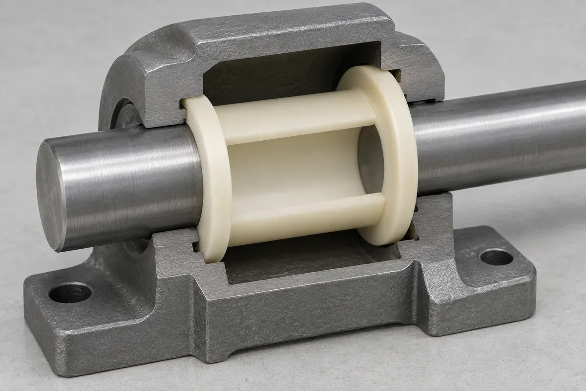
Measure the housing before assembly and preserve its identity. Compare installed results across the relevant permitted housing and sleeve conditions. Do not assign a result to a molding cavity when the test housings also changed without a record.
For nylon or another condition-sensitive candidate, record the specimen history. See the moisture and fit review. A fit study needs a consistent condition before it can distinguish geometry from environmental response.
If the shaft is misaligned between two supports, a tight-feeling assembly may not be a bore-size issue at all. Check the common axis and the way both housings are mounted. Enlarging one sleeve can disguise a positional problem while introducing unwanted movement.
Release the fit, not only the loose drawing
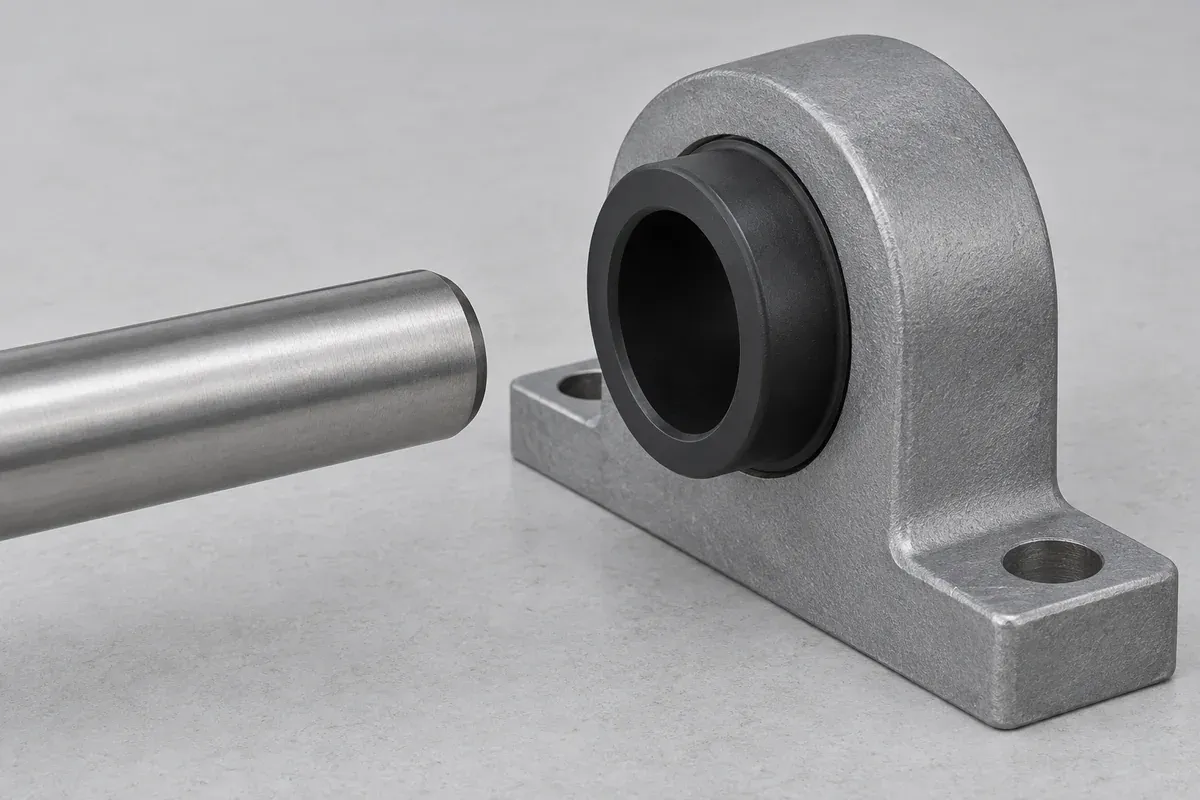
The corrective action might involve housing limits, sleeve geometry, material, lead-in or installation practice. Choose it from the evidence. Document what changed and repeat the checks affected by that change rather than claiming that one successful assembly proves every combination.
For a quotation, provide both loose-part requirements and the intended installed function. State who supplies the inspection housing and shaft, which revisions govern, and what records are needed. This makes sample approval a shared assembly decision rather than an argument over one unqualified diameter.
Turn the review into a defined molding scope
Explore our custom injection-molded plastic bushings and the related illustrative engineering study. Send the drawing revision, counterpart details, intended use and the decisions still open. Development samples and production approval should have separate, agreed deliverables.