
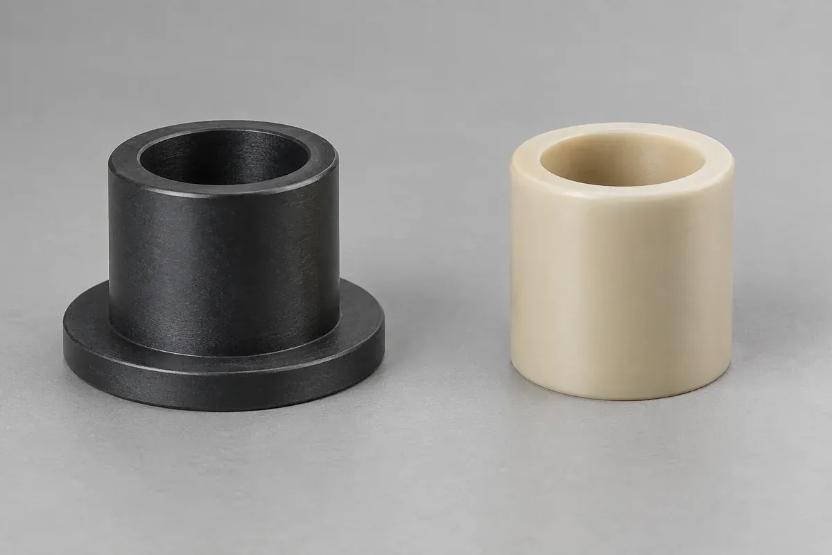
Product design illustrations. Final geometry, materials and acceptance criteria are project-specific.
A flange is not just a larger end on a sleeve. It changes how the bushing can locate axially, contact a mating face and be installed. Decide whether the assembly needs radial guidance only or also has a defined axial interface before choosing the familiar-looking shape from a catalogue.
For a custom molded part, compare the complete assembly. A straight sleeve plus a separate washer may be appropriate in one layout, while an integral flange may simplify another. Neither arrangement is automatically cheaper, stronger or more accurate without the geometry, loading and order scope.
Separate the radial and axial jobs
The cylindrical bore typically guides the shaft radially. A flange can locate the bushing against a housing face and may be designed to participate in an axial contact. Those are separate functions. A flange shown on a drawing does not, by itself, establish a thrust rating or a suitable sliding surface.
Identify which member rotates or moves relative to each surface. If a shoulder bears on the flange, define its contact area, finish, loading and motion. If the flange only prevents the sleeve from being inserted too far, avoid adding unnecessary thrust-performance claims to the purchase specification.
Mark the reference face used for axial location. A molded flange with local warp or an uncontrolled gate witness may not seat as assumed. The housing face and the permitted contact condition belong in the same drawing review.
Decide what prevents unwanted movement
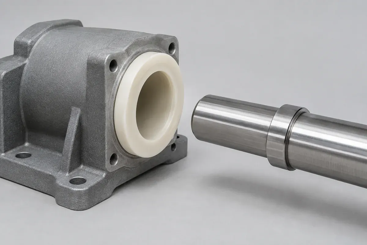
A sleeve requires an intentional retention strategy if it must not move axially or rotate in the housing. Interference, shoulders, clips or other features may be considered, but the geometry and material determine what is feasible. A close fit should not silently stand in for a retention requirement.
For a flange, check whether it can lift away from its seat in the opposite direction. It stops movement toward one face only when that face is actually engaged. Assembly drawings should show how the full sequence constrains the bushing, including any shaft or washer that completes the retention.
igus's plain-bearing tolerance guidance distinguishes installed conditions from loose-part dimensions. The same review principle is useful here, without importing the proprietary product's tolerance recommendations into an unrelated custom geometry.
Check installation and removal access
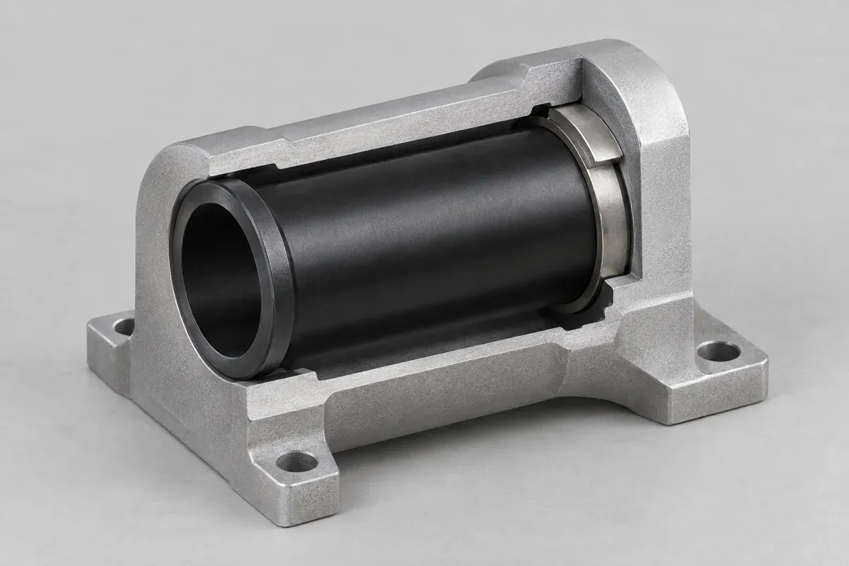
Look at which side of the housing is accessible. A flange that locates neatly in CAD may obstruct the proposed insertion tool or prevent the shaft from being assembled. Check adjacent components, press access, lead-in geometry and the surfaces available to support the housing during installation.
Consider servicing if the part is intended to be replaceable. A feature that permanently traps the sleeve may be acceptable for one assembly but unsuitable for another. Define whether removal can damage the old bushing and whether the housing must remain reusable.
Do not infer sealing from a flange sitting against a face. A bearing geometry and a seal geometry perform different jobs. If dust or liquid exclusion is required, include a defined sealing solution and separate evidence rather than describing a flanged bearing as sealed.
Bring the geometry into the molding review
The transition from sleeve wall to flange affects the molded part and tool. Review wall changes, radii, gate location, mold split and ejection with the critical bore and seating face identified. A custom tab or anti-rotation feature also needs a credible release direction.
Define which features can change during DFM. If the outside diameter is constrained by an existing housing, moving that surface to improve molding may be unacceptable. If only the envelope is fixed, an alternative geometry might preserve the function with a simpler tool.
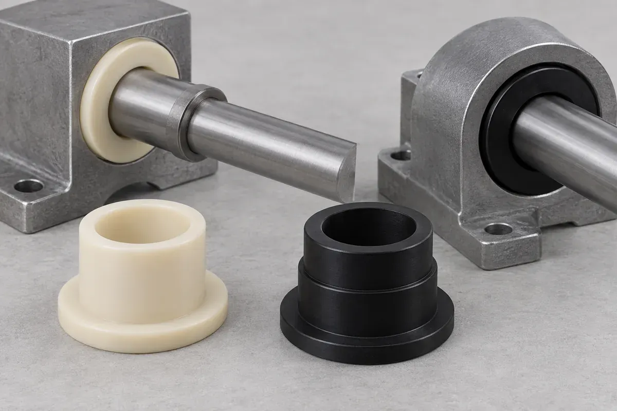
For sampling, inspect the agreed loose features and then the installed relationship. Use the press-fit guide where interference is proposed. Record seating, permitted motion and shaft access under the same counterpart revisions. That turns “flanged or straight” into an engineering choice with a clear manufacturing scope.
If both concepts meet the initial geometry, compare tooling, installation effort, secondary components and the required evidence. The simplest delivered part is not necessarily the simplest complete assembly. Keep that distinction visible when asking suppliers to price alternatives.
Turn the review into a defined molding scope
Explore our custom injection-molded plastic bushings and the related illustrative engineering study. Send the drawing revision, counterpart details, intended use and the decisions still open. Development samples and production approval should have separate, agreed deliverables.