
Custom molded parts · Made to your design
Custom Injection-Molded Plastic Impellers
Connect the hydraulic geometry to an achievable molding and assembly route.
Send the impeller drawing, mating shaft and housing details for a manufacturing review. We assess material candidates, blade geometry, mold release and any separately agreed joining or finishing. Finished-pump performance is validated in the defined customer system, not inferred from a molded part photograph.
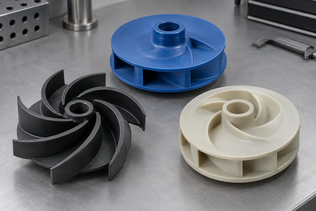
Product details
Plastic Impellers: product details
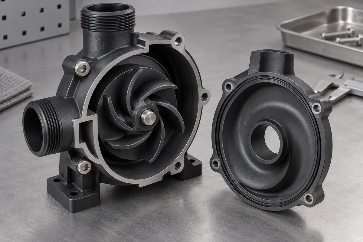
Product design illustrations showing component features and assembly relationships. The final geometry is made to your approved drawing.
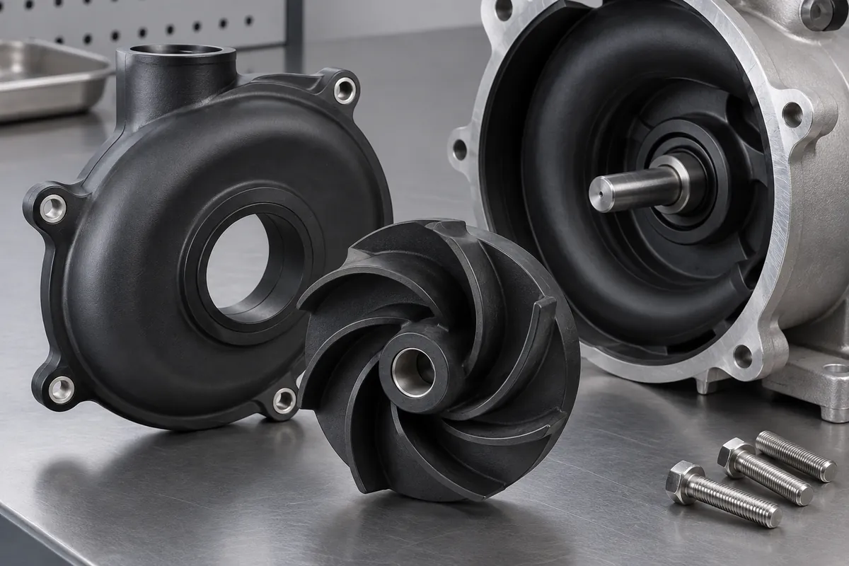
Blade geometry
Preserve the flow surfaces while reviewing molding transitions.
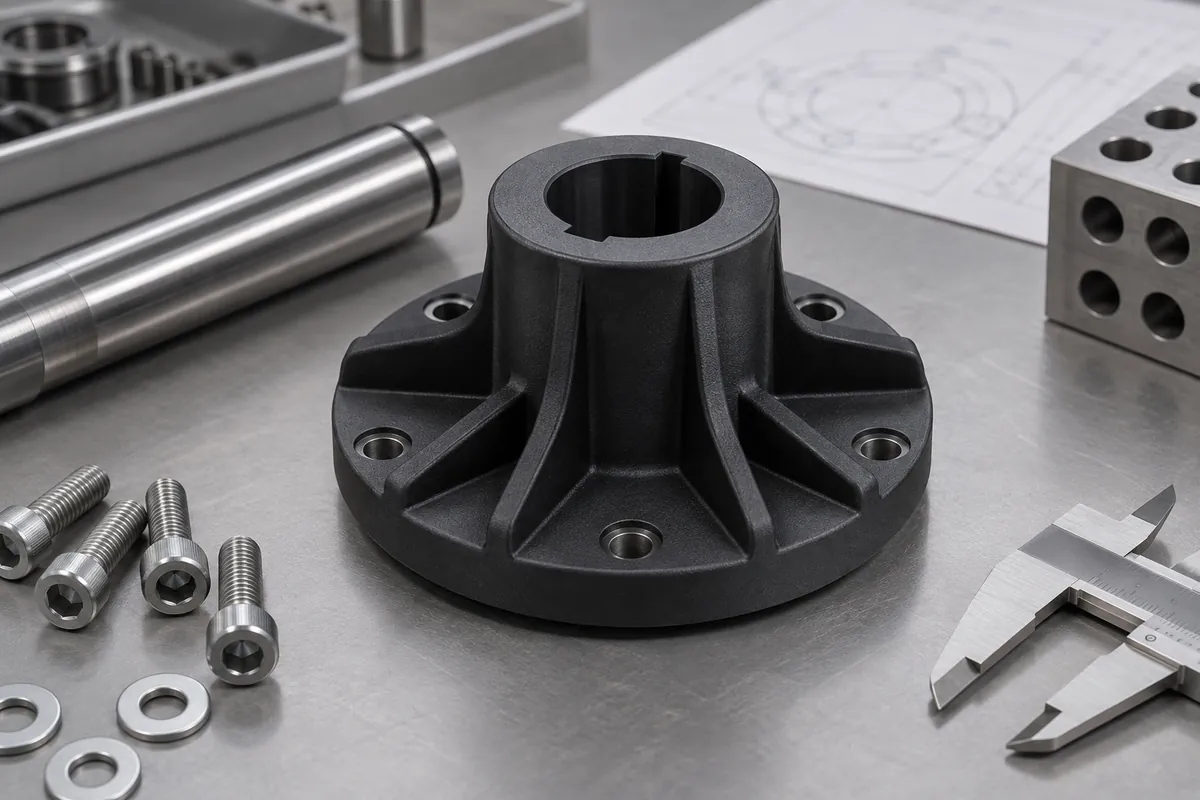
Shaft opening
Define the finished bore and its relationship to the rotating datums.
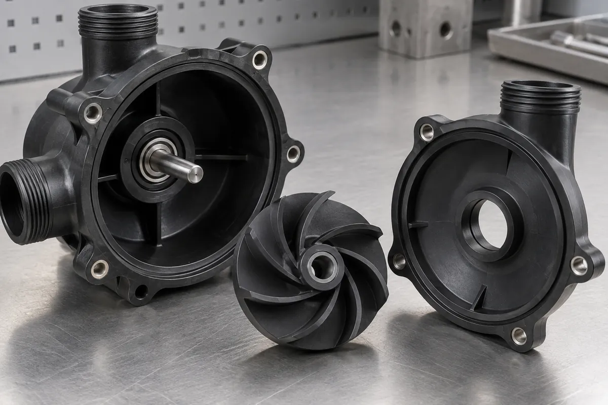
Joined construction
Locate and inspect the sections before the passages are closed.
Internal passages
Agree which features are checked before and after joining.
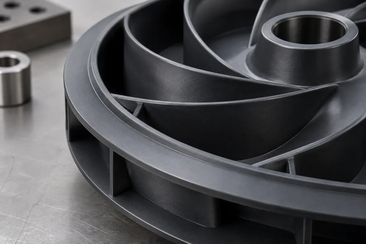
Outer rim
Control the clearance envelope and permitted correction regions.
Illustrative configurations. Final specifications follow your approved drawings.
Application fit
A custom component with a defined purpose
Connect the hydraulic geometry to an achievable molding and assembly route.
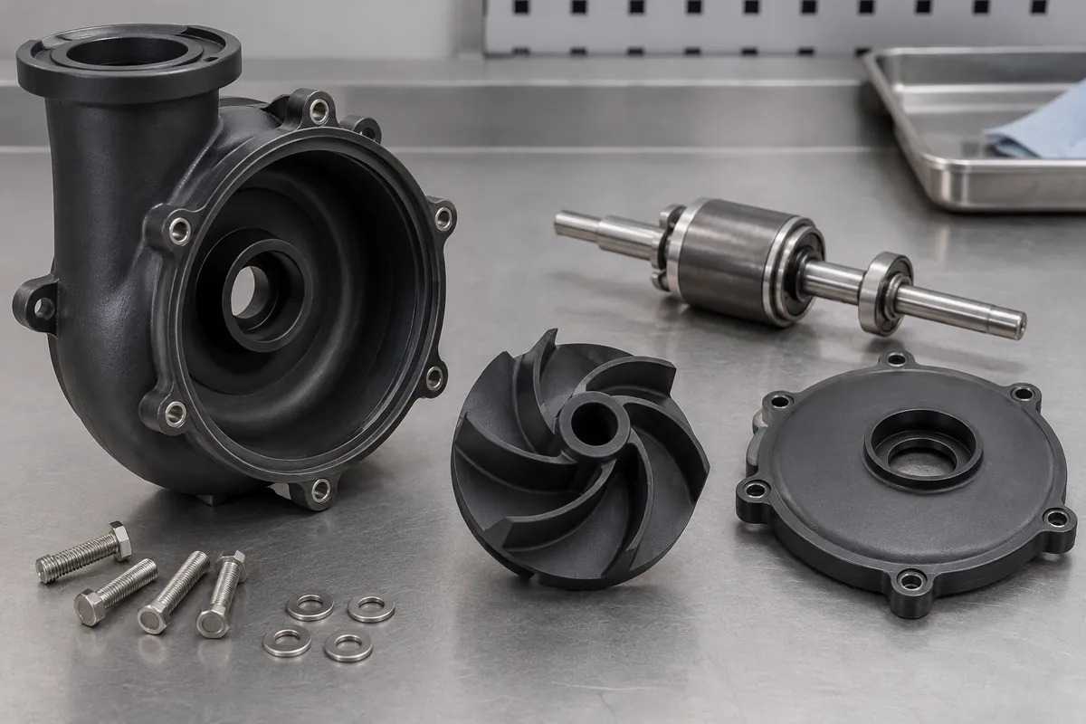
Open impellers
Blade and hub geometries with project-specific material and inspection requirements.
Joined closed impellers
Separately molded sections where joining provides a feasible route to enclosed passages.
Shaft-interface components
Hubs and connection details with defined fit, torque transfer and axial retention.
Quote-ready inputs
What to send for a meaningful quotation
Use the same drawing and requirements for every proposal. Mark open decisions explicitly so that a low price does not conceal a different deliverable.
| Area | Please provide | Review before release |
|---|---|---|
| Project definition | Current CAD, drawing revision, mating components and quantities. | Mark fixed interfaces and open design decisions before comparing quotations. |
| Operating duty | Fluid, temperature, speed and intended operating envelope. | Material and pump-system validation remain separate. |
| Construction | Hydraulic no-change surfaces and permitted split or joining features. | Confirm core release and the finished assembly sequence. |
| Rotating checks | Bore datums, runout, balance method and correction zones. | A balance grade is not a pump vibration measurement. |
| Supply and release | Trial, first-order and repeat quantities, packing and report needs. | Agree tooling scope, approval hold points and change control. |
From drawing to approval
From the assembly requirement to production approval
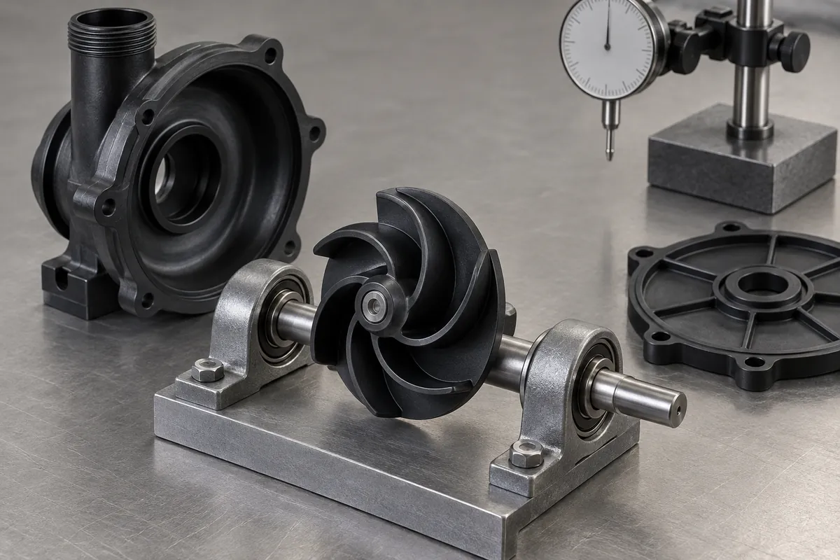
Align the scope
Freeze the hydraulic interfaces, review resin and tooling, validate any joined construction, then complete bore and rotating checks before system approval.
Review the tool and material
Confirm the exact compound, molding route and any secondary operations. Resolve proposed changes against the functional drawing before tooling release.
Evaluate identified samples
Record cavity and lot identity with dimensional and agreed functional observations. Keep incomplete validation separate from completed acceptance.
Release the approved configuration
Retain the drawing, material, process route and inspection method. Review later changes against the configuration that was actually approved.
Practical engineering and buying guides
Decisions to make before production
- Plastic Impeller Materials: PP, PA, PPS or PEEK?Compare PP, PA, PPS and PEEK for molded pump impellers using fluid exposure, operating temperature, blade geometry and shaft interfaces. Select exact grades.
- Open vs Closed Impellers: Molding and Assembly Trade-OffsCompare open and closed injection-molded impellers through flow-path access, mold release, welded construction and inspection. Do not assume closed passages are one-piece molded.
- Impeller-to-Shaft Connections: Press Fits, Inserts and KeywaysReview molded impeller shaft connections through torque transfer, retention, bore condition, inserts and assembly loads. Match inspection to the delivered state.
- Plastic Impeller Runout and Balance: Separate MeasurementsDistinguish impeller runout, rotor balance and pump vibration. Define mounting references, balancing speed, sample scope and correction before accepting a report.
- Thin Impeller Blades: Filling, Weld Lines and WarpageReview thin molded impeller blades for filling, cooling, weld regions, support and warpage. Preserve hydraulic geometry while making the design manufacturable.
- Validating a Molded Impeller in the Pump AssemblyValidate a molded impeller in its pump assembly with controlled configuration, operating points, fluid conditions and separate component acceptance records.
Before you request a quote
Are closed impellers always molded in one piece?
No. Enclosed geometry may require separately molded sections and joining or another specially reviewed tooling route.
Does balancing prove the pump will run without vibration?
No. The complete rotating assembly and operating conditions also matter. Component balance and pump validation are different checks.
Can you assign a standard pressure or temperature rating?
Not without the exact grade, geometry, fluid and validation conditions. Requirements are established per project.
Your next step
Discuss the part with its intended function.
Send the plastic impellers drawing with its mating interfaces and acceptance requirements. We will review the proposed molding scope and identify the information needed for a meaningful quotation.
Explore our injection molding service or review other custom molded applications.