
Custom molded parts · Made to your design
Custom Injection-Molded Plastic Optics
Separate optical design requirements from the measurements used to approve the molded part.
Send the optical and mechanical drawings together with the aperture, wavelength range and inspection methods. We review molded polymer components with their mounting and handling needs. Specialized form and system-performance claims require actual measurement evidence, not only a polished tool or transparent sample.
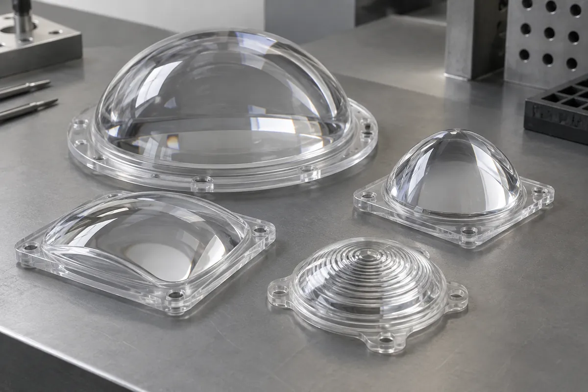
Product details
Plastic Optics: product details
Product design illustrations showing component features and assembly relationships. The final geometry is made to your approved drawing.
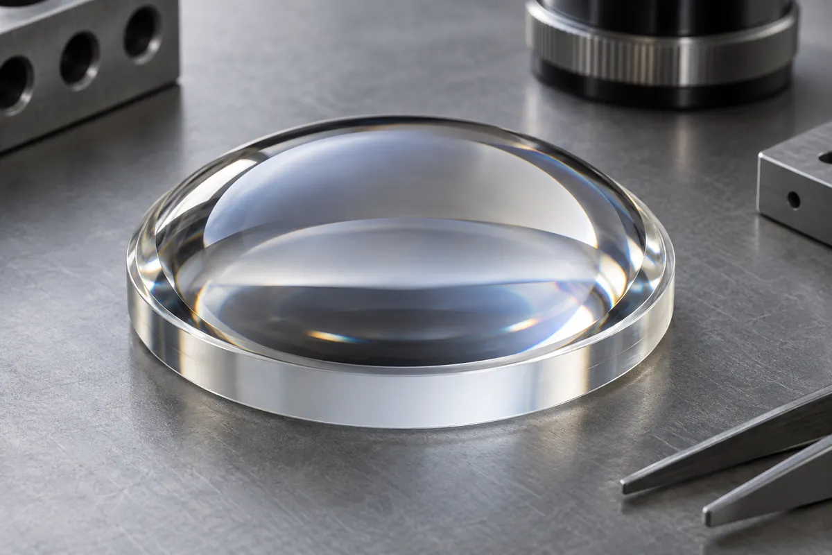
Optical surface
Identify the intended form and its verification method.
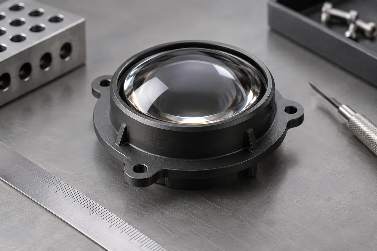
Mounting flange
Keep location and retention outside the controlled aperture where feasible.
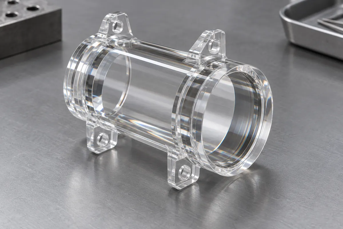
Integrated support
Review mechanical features without compromising the optical path.
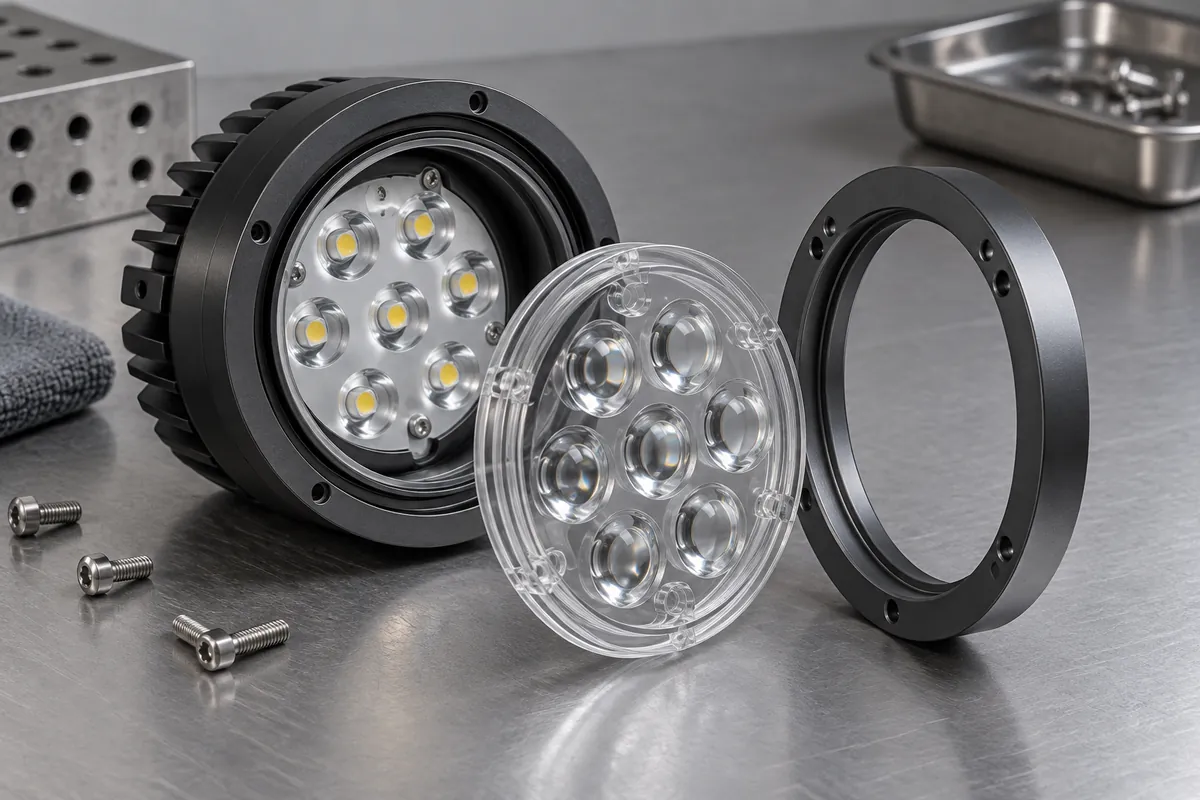
Bezel relationship
Evaluate the mounted condition and permitted assembly load.
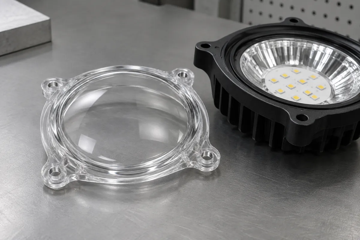
Gate region
Define the allowed vestige and finishing outside the working surface.
Illustrative configurations. Final specifications follow your approved drawings.
Application fit
A custom component with a defined purpose
Separate optical design requirements from the measurements used to approve the molded part.
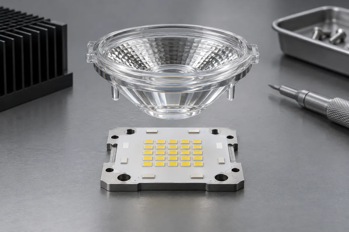
Illumination lenses
Custom lens geometries for an identified source and mounting arrangement.
Optical interface components
Transparent parts with integrated locating flanges or support features outside the working aperture.
Molded windows and covers
Defined optical and cosmetic zones with project-specific material and exposure requirements.
Quote-ready inputs
What to send for a meaningful quotation
Use the same drawing and requirements for every proposal. Mark open decisions explicitly so that a low price does not conceal a different deliverable.
| Area | Please provide | Review before release |
|---|---|---|
| Project definition | Current CAD, drawing revision, mating components and quantities. | Mark fixed interfaces and open design decisions before comparing quotations. |
| Optical definition | Surface prescription, clear aperture, wavelength and performance target. | Specify form, roughness and surface quality separately. |
| Mechanical interfaces | Mounting datums, fit, gate restrictions and handling zones. | Review assembly-induced stress as well as free-state dimensions. |
| Measurement | Methods, specimen geometry, source conditions and cavity sampling. | An integrating-sphere flux result is not beam-uniformity evidence. |
| Supply and release | Trial, first-order and repeat quantities, packing and report needs. | Agree tooling scope, approval hold points and change control. |
From drawing to approval
From the assembly requirement to production approval
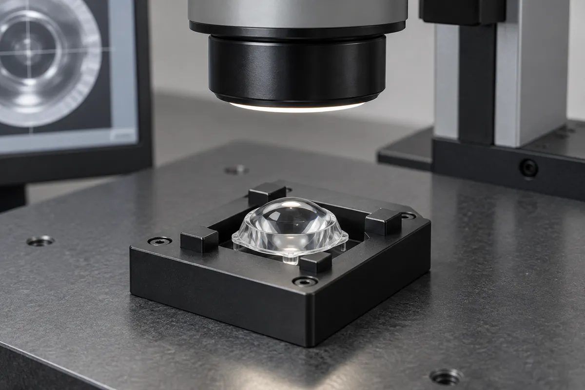
Align the scope
Align optical and mechanical requirements, review material and tool interfaces, inspect cavity-identified samples, and separate component acceptance from system qualification.
Review the tool and material
Confirm the exact compound, molding route and any secondary operations. Resolve proposed changes against the functional drawing before tooling release.
Evaluate identified samples
Record cavity and lot identity with dimensional and agreed functional observations. Keep incomplete validation separate from completed acceptance.
Release the approved configuration
Retain the drawing, material, process route and inspection method. Review later changes against the configuration that was actually approved.
Practical engineering and buying guides
Decisions to make before production
- PMMA vs Polycarbonate Lenses: Optical Duty and MoldingCompare PMMA and polycarbonate for molded lenses using optical function, impact, temperature, coatings and assembly stress. Choose an exact grade and validation method.
- Haze vs Transmission in Molded Plastic OpticsDistinguish haze, transmission and assembled optical output in molded plastic optics. Define wavelength, specimen geometry, collection method and conditioning before comparing results.
- Birefringence in Molded Optics: What Buyers Should SpecifyUnderstand birefringence checks for injection-molded optics. Relate polarized observations to material, geometry, molding and assembly without treating fringe color as a universal pass rule.
- Gates and Parting Lines Around Optical SurfacesPlan gates, parting lines and ejection around optical clear apertures and mounting features. Preserve inspectable surfaces while making a molded lens manufacturable.
- Specifying Scratches, Digs and Cosmetic Zones on Plastic OpticsSpecify cosmetic zones, scratches and digs on molded plastic optics with a named method and viewing conditions. Keep appearance, surface form and optical performance distinct.
- Inspecting Molded Optics: Dimensions vs Optical PerformanceBuild a molded-optics inspection plan separating dimensions, surface form, appearance, transmission, total flux and beam distribution. Publish only results supported by the actual method.
Before you request a quote
Does SPI A2 polishing prove a quarter-wave surface?
No. Tool finish and measured molded surface form are different properties. A wavefront or form claim needs an appropriate report.
Can total flux verify beam uniformity?
No. Spatial distribution requires a suitable spatial measurement setup; total flux is a different quantity.
Are illustrations photographs of delivered optics?
No. The product images illustrate design features. A custom quotation and acceptance plan are based on the supplied drawings and requirements.
Your next step
Discuss the part with its intended function.
Send the plastic optics drawing with its mating interfaces and acceptance requirements. We will review the proposed molding scope and identify the information needed for a meaningful quotation.
Explore our injection molding service or review other custom molded applications.