
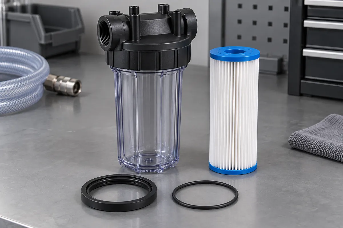
Product design illustrations. Final geometry, materials and acceptance criteria are project-specific.
A filter housing can remain dry on the outside while failing to route all fluid through the intended filtration element. Internal bypass may occur at an end seal, seat or other interface. Containment and filtration therefore need separate reviews, even when both depend on the same molded housing.
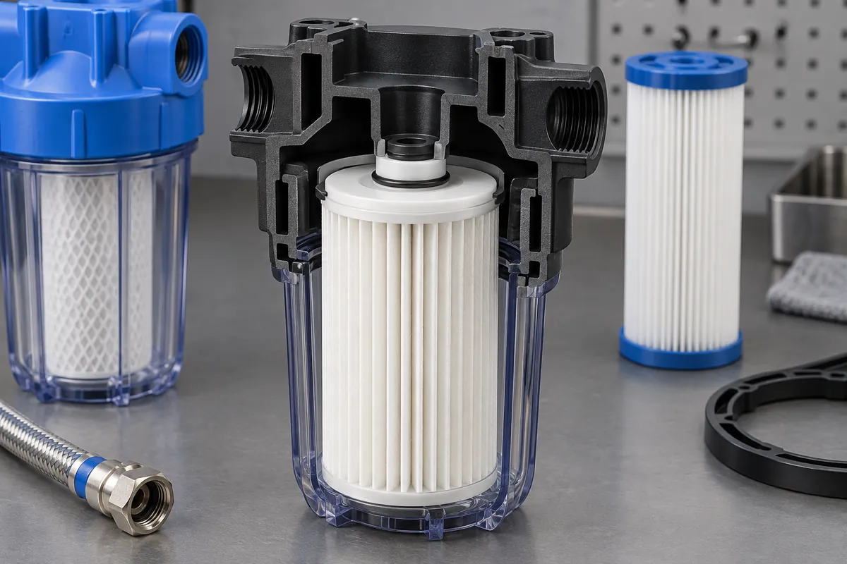
Begin with the intended flow path and cartridge construction. Identify the dirty-side volume, clean-side volume and every interface separating them. Then trace how the cartridge is located and compressed when the closure reaches its approved position, rather than assuming the nominal CAD contact is a working seal.
Define location, support and sealing
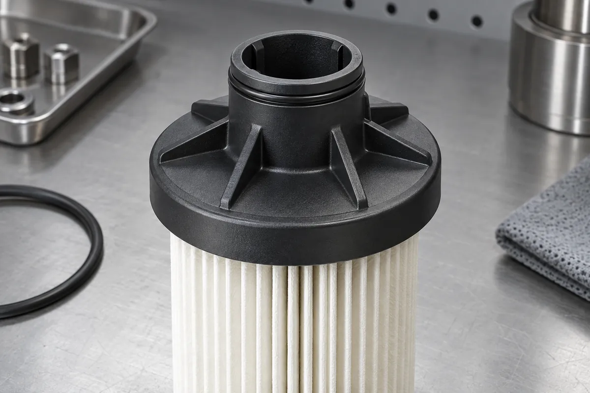
The cartridge may need axial support, radial location and a sealing contact, each provided by different features. A locating boss is not automatically a sealing surface, and an end seal should not accidentally become the only structural support unless that is the approved design.
Review the tolerance stack between the cartridge and housing. Cartridge length, end-cap geometry, seal dimensions and closure position can all affect the assembled condition. Checking each nominal dimension independently does not establish that all allowed combinations will produce acceptable engagement.
Include the cartridge's condition after relevant exposure. Fluid, temperature and pressure can change the way components interact. If the housing is intended for replacement cartridges from more than one source, verify the controlled interface rather than relying on a broad nominal size description.
Look for bypass paths beyond the obvious seat
Inspect whether flash, warpage or surface damage can interrupt a contact region. A small local defect may matter more than a favorable average diameter. Mark the critical interface on the drawing so molding and finishing reviews concentrate on the surfaces that actually separate the fluid paths.
Consider cartridge installation and the possibility of incomplete seating. A closure that can be tightened with a misplaced cartridge may conceal an assembly error. Practical locating or mistake-proofing features should be assessed without introducing new restrictions that damage the cartridge during installation.
The seal design should follow relevant manufacturer guidance, such as the Parker O-Ring Handbook where an O-ring is used. The selected interface still needs validation in the finished filter assembly.
Do not confuse pressure drop with filtration performance
Pressure drop describes a flow-related response under stated conditions; it does not by itself establish contaminant removal or absence of bypass. A low restriction could reflect an intended flow path or an unintended one. Interpret the reading with the complete test arrangement and purpose in view.
Likewise, an external leak test evaluates containment at the selected boundary. It may not reveal fluid passing around the cartridge inside the housing. Define the test needed to evaluate the internal separation and the filtration claim rather than assuming one pressure check covers all requirements.
Keep cartridge media performance distinct from housing manufacture. The molded-component supplier may control the seat and support geometry while another party defines media efficiency and complete filter qualification. Agree those responsibilities so no essential verification is omitted between suppliers.
Define how a missing, reversed or incorrect cartridge will be detected. The appropriate control may be mechanical, procedural or part of system validation rather than a molded feature alone. The housing design should support that control, especially when several cartridge variants share a similar external envelope but have different sealing interfaces.
Validate the service configuration
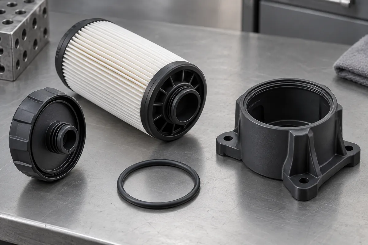
Test representative assemblies at the required flow and exposure conditions using controlled cartridge specimens. Record component revisions, assembly method and sample count. If the housing is reopened in service, repeat the relevant checks after the agreed maintenance operations and seal replacement procedure.
Review the choice between threaded and welded housings in this context. A permanent joint may prevent later cartridge movement but also remove access for inspection; a serviceable closure adds repeatability requirements at each maintenance cycle.
Release the housing with clear interface dimensions and explicitly assigned system tests. This keeps the commercial offer honest: manufacturing a defined plastic body is not the same as certifying a complete filtration system, but a well-controlled body gives that system validation a reliable starting point.
Discuss the component and its acceptance requirements
Explore our custom plastic filter housings and the related project case study. Send the current drawing, mating-part details, operating conditions and required quantities. We can review tooling, molding and inspection as a defined supply scope, with development samples and production approval kept separate.