
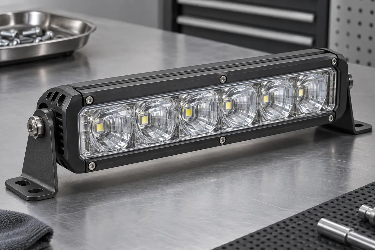
Product design illustrations. Final geometry, materials and acceptance criteria are project-specific.
A molded optic needs a practical route for material to enter the cavity and for the finished part to leave it. Gates, parting lines and ejection features therefore cannot be treated as afterthoughts. Their placement should follow the optical working area and mounting geometry, with acceptable residual features defined before tool manufacture.
Begin by marking the clear aperture and the surfaces that control optical function. Separate those areas from mounting rims, locating tabs and cosmetic zones. Without that map, the tool designer may choose a convenient gate or ejector location that interferes with the intended optical path.
Use nonoptical features deliberately
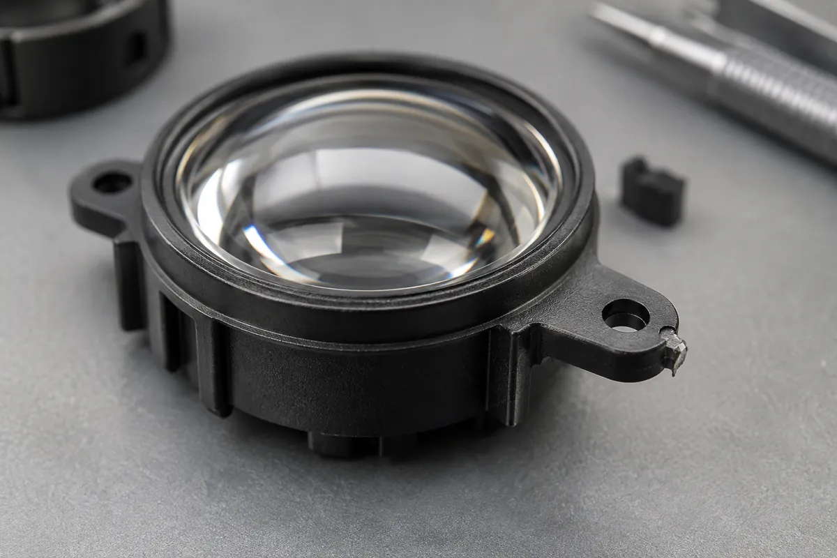
A peripheral flange or tab can provide a location for gating, handling or ejection, but it must remain compatible with the assembled space. Adding such a feature changes the component and may affect stress or cooling. Review it with both the optical and mechanical design teams.
Specify the permitted gate remnant and trimming condition. A statement such as gate outside the aperture does not establish whether a residual projection can foul the holder or create loose particles. Define the relevant limit and how the finished feature will be inspected.
The distinction between surface form, surface quality and other optical requirements is explained in Edmund Optics' specification guidance. A gate-location review should protect the actual required function rather than treating all polished surfaces as equivalent.
If a cavity is repolished or a gate insert is replaced, inspect more than the repaired area. Tool maintenance can alter nearby transitions or the way the part fills and releases. The reapproval scope should follow the affected functions and preserve the relationship between the optical aperture, mounting features and manufacturing references.
Review parting and release together
A parting line can introduce mismatch or flash where mold sections meet. Its importance depends on whether it crosses an optical region, a locating surface or a noncritical edge. Specify the acceptable condition by zone instead of using a broad appearance instruction that leaves the functional boundary unclear.
Ejection must remove the part without unacceptable marking or distortion. The available support and contact surfaces need review, especially for thin or highly polished features. A tool concept that forms the nominal geometry but damages it during release is not a complete manufacturing solution.
Consider the handling sequence immediately after release. Contact with a tray, gripper or stacking surface can mark an optic before formal inspection begins. The component should have a defined way to move through production without using the clear aperture as a convenient handling surface.
Keep flow and stress in the review
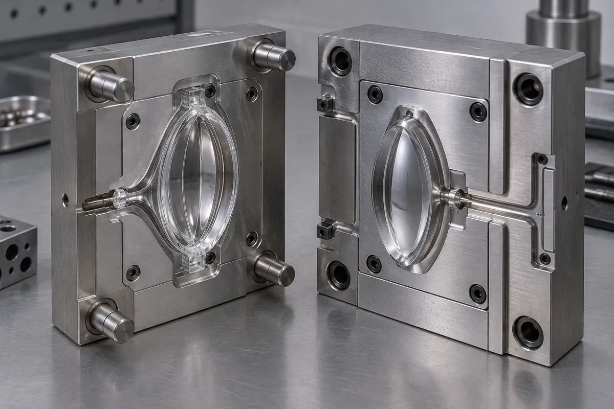
Moving a gate away from the optical area may change the flow path or local section requirements. Evaluate those consequences rather than assuming farther away is always better. The proposed route needs to produce the required shape and optical condition as well as a visually discreet gate location.
Review weld regions, trapped gas and other filling concerns with the supplier. Simulation can guide the discussion when its material and boundary assumptions are known. Trial molding and appropriate inspection are still needed to establish what the proposed process actually produces.
Check the effect of any trimming or finishing on the final part. A secondary operation can introduce stress, debris or surface damage. Include it in the sample approval so the inspected specimen represents the same route intended for repeat production.
Make acceptance practical and traceable
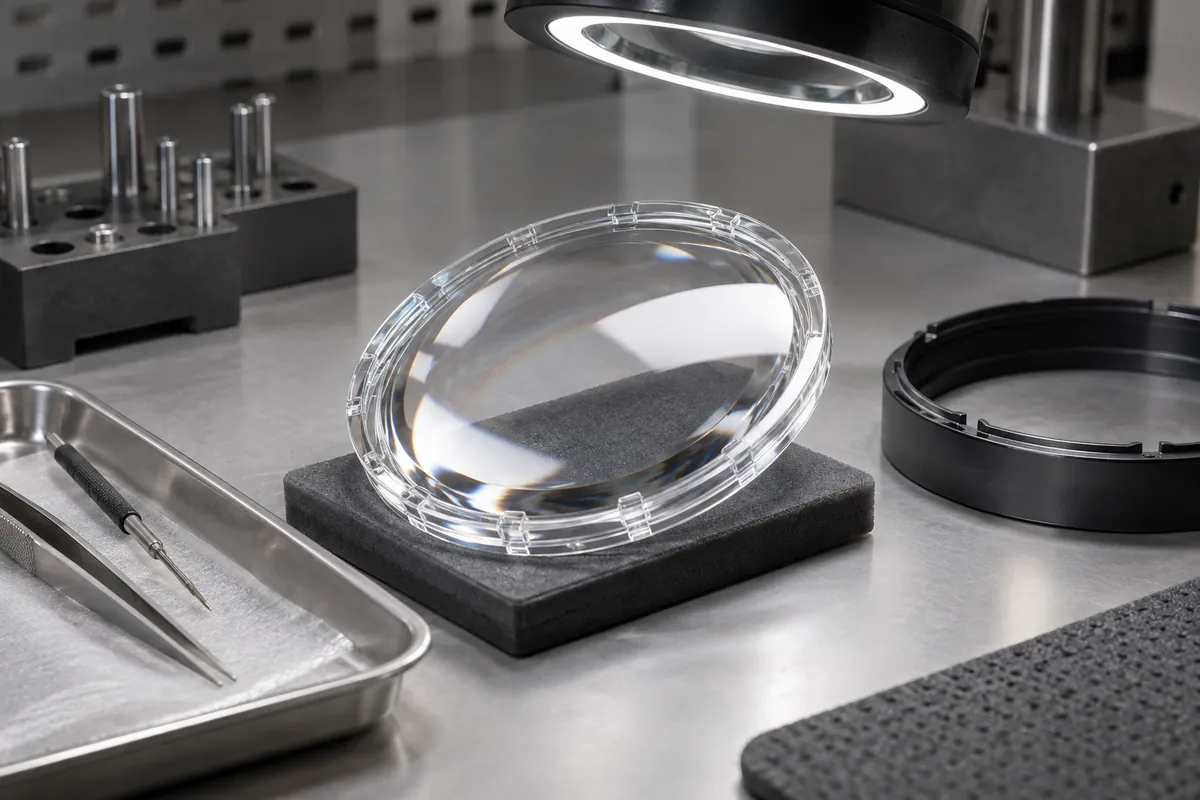
Use drawings or controlled reference samples to identify acceptable residual features. State lighting and viewing conditions for visual checks where appropriate. An informal instruction to make the lens perfect is difficult to inspect consistently and can conceal which defects actually affect the system.
Coordinate the review with scratch, dig and cosmetic-zone requirements. These should complement dimensional and optical-performance checks rather than replacing them with a single subjective appearance judgment.
Keep the approved gate, parting and ejection arrangement with the tool release. If maintenance or a future cavity changes those features, reassess the relevant optical and assembly requirements. This preserves the connection between a manufacturable tool and the component configuration that was actually validated.
Discuss the component and its acceptance requirements
Explore our custom plastic optics and the related project case study. Send the current drawing, mating-part details, operating conditions and required quantities. We can review tooling, molding and inspection as a defined supply scope, with development samples and production approval kept separate.