
Product design illustrations. Final geometry, materials and acceptance criteria are project-specific.
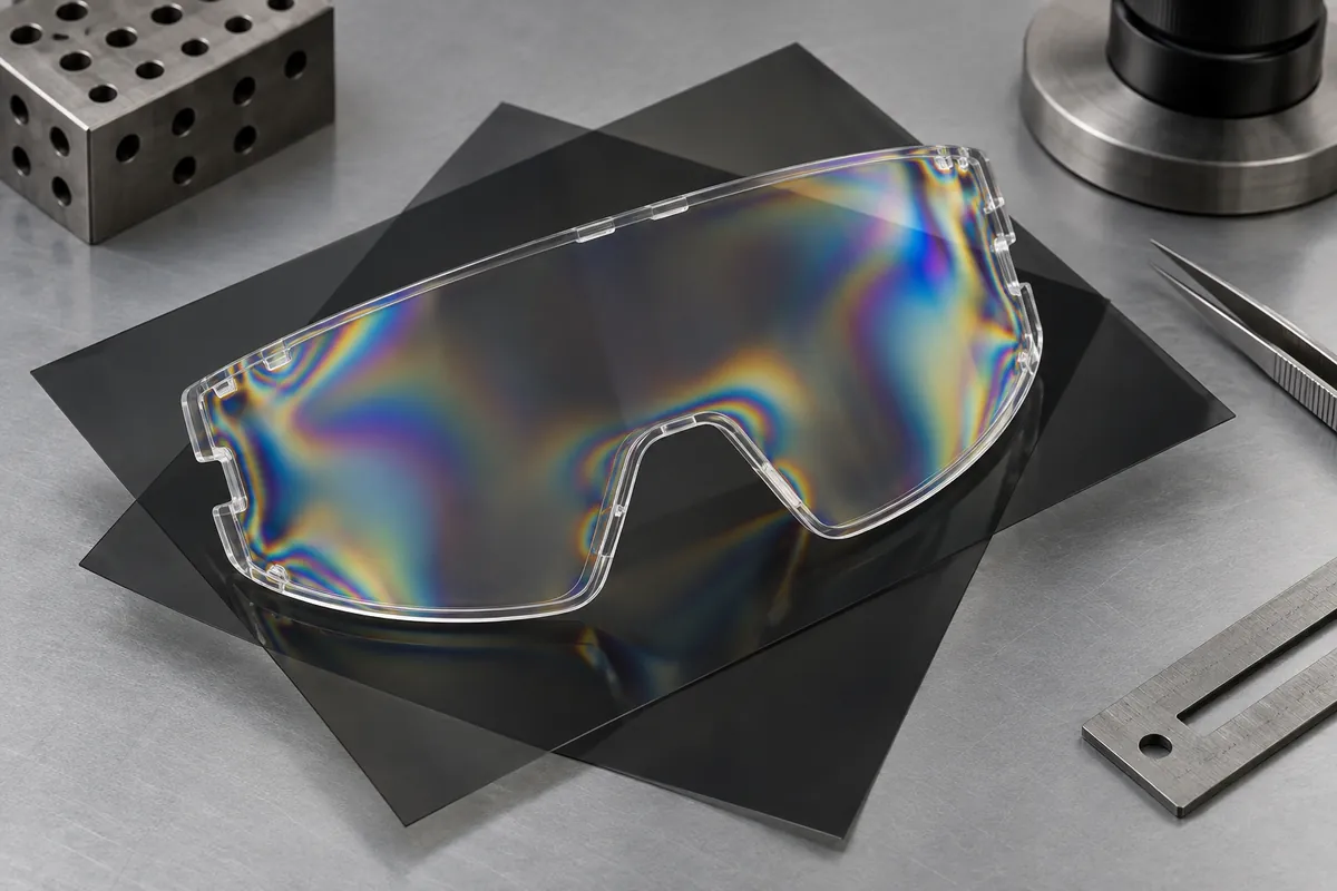
A transparent molded part may look clear under ordinary light and show a strong pattern between polarizers. That observation can reveal optical behavior associated with material orientation or stress, but interpreting it requires a defined setup and an understanding of the material. A colorful image is not itself a calibrated stress report.
First establish why birefringence matters to the application. A polarization-sensitive optical system may have requirements different from a simple illumination cover. The acceptable condition should come from the optical design and validation plan rather than a general rule that every visible fringe is unacceptable.
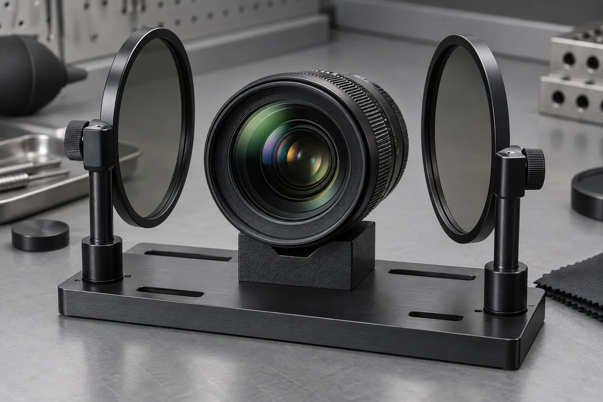
Use polarized inspection as a defined method
Record the illumination, polarizer arrangement, specimen orientation and relevant wavelength conditions. Changing these can change the observed pattern. Photographs taken under different setups should not be ranked as though they were direct numerical measurements of the same physical quantity.
Covestro's photoelastic stress-analysis guidance explains the relationship used for polycarbonate evaluation. Applying such a method quantitatively requires the appropriate material information and test interpretation, not just a visual comparison of colors.
Keep thickness and geometry in view. Optical path length can influence the observation, so a thick hub and a thin window may not be directly comparable. Define the region and purpose of the inspection before deciding what constitutes an unfavorable pattern.
Investigate molding factors without assuming one cause
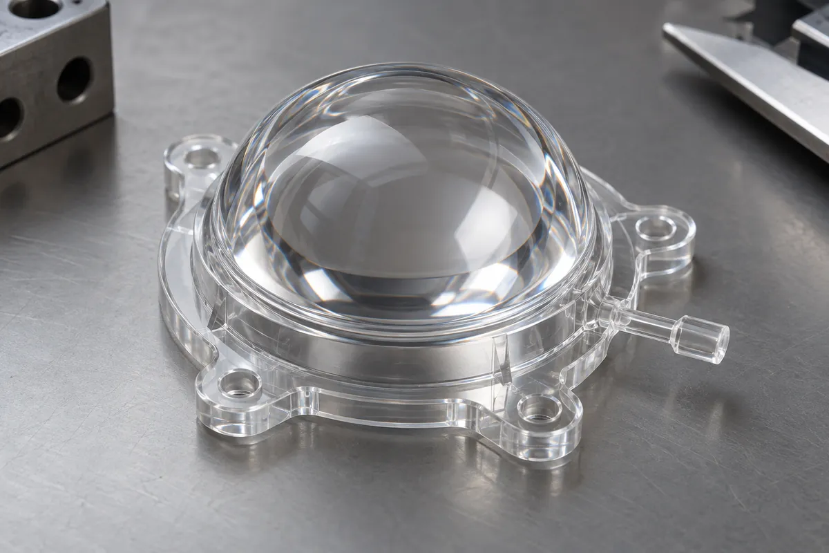
Gate location, flow history, section changes and cooling can all be relevant to a transparent molded component. Review their relationship to the observed region rather than immediately changing one process setting. A pattern near a gate may suggest a useful investigation, but it is not a complete root-cause conclusion.
Check whether the compared samples share the same material, tool and processing history. A change in grade or geometry can alter the interpretation. Retain specimen and cavity identity so an apparent improvement can be connected to a controlled change rather than a different sample population.
Use a deliberate trial plan when adjusting the process. Changing temperature, pressure and cooling simultaneously may produce a better-looking sample without explaining which factor matters. The resulting process still needs confirmation that dimensions, appearance and other requirements remain acceptable.
Do not overlook assembly-induced effects
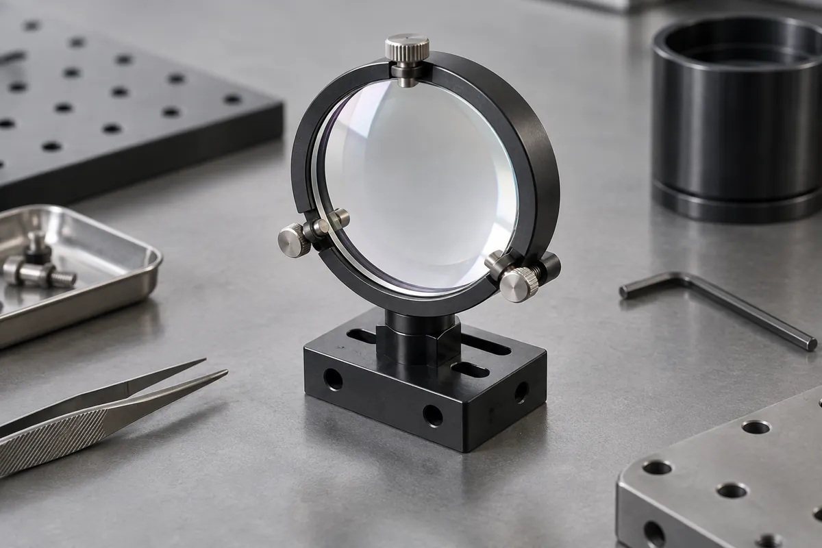
A free-state optic can change when installed in a tight holder or bonded into an assembly. Compare the defined free and mounted conditions where the application requires it. A successful molding inspection cannot rule out stress introduced later by clamps, fasteners or thermal mismatch.
Review how the mount locates and retains the optic. Uncontrolled interference or uneven contact can distort the component. If the optical region is sensitive, the assembly design should establish a repeatable constraint rather than relying on the installer to tighten until the part feels secure.
Include the operating environment if temperature or exposure changes the assembly relationship. A room-temperature mounted check may not cover the full duty. State the conditions actually evaluated so the result is not interpreted as a guarantee for every installation.
Define how images from polarized inspection will be stored and compared. Exposure settings or image enhancement can alter their apparent intensity, making a visual trend misleading. Preserve a consistent acquisition method and the original records where comparison is part of process control, rather than using edited marketing images as inspection evidence.
Close the relevant optical requirement
Use polarized inspection as part of a broader plan that includes the required optical performance. A reduction in observed fringe intensity is useful only in context; it does not automatically prove improved imaging, transmission or mechanical durability. Measure the outcome that matters to the system.
Coordinate this work with material selection and the mounting design. The best process adjustment cannot compensate for every mismatch between material, geometry and assembly requirements.
Release an agreed method, acceptance boundary and specimen condition. If the available evidence is qualitative, describe it as qualitative rather than inventing a numerical stress or retardation limit. This preserves the value of the inspection without claiming more precision than the setup provides.
Discuss the component and its acceptance requirements
Explore our custom plastic optics and the related project case study. Send the current drawing, mating-part details, operating conditions and required quantities. We can review tooling, molding and inspection as a defined supply scope, with development samples and production approval kept separate.