
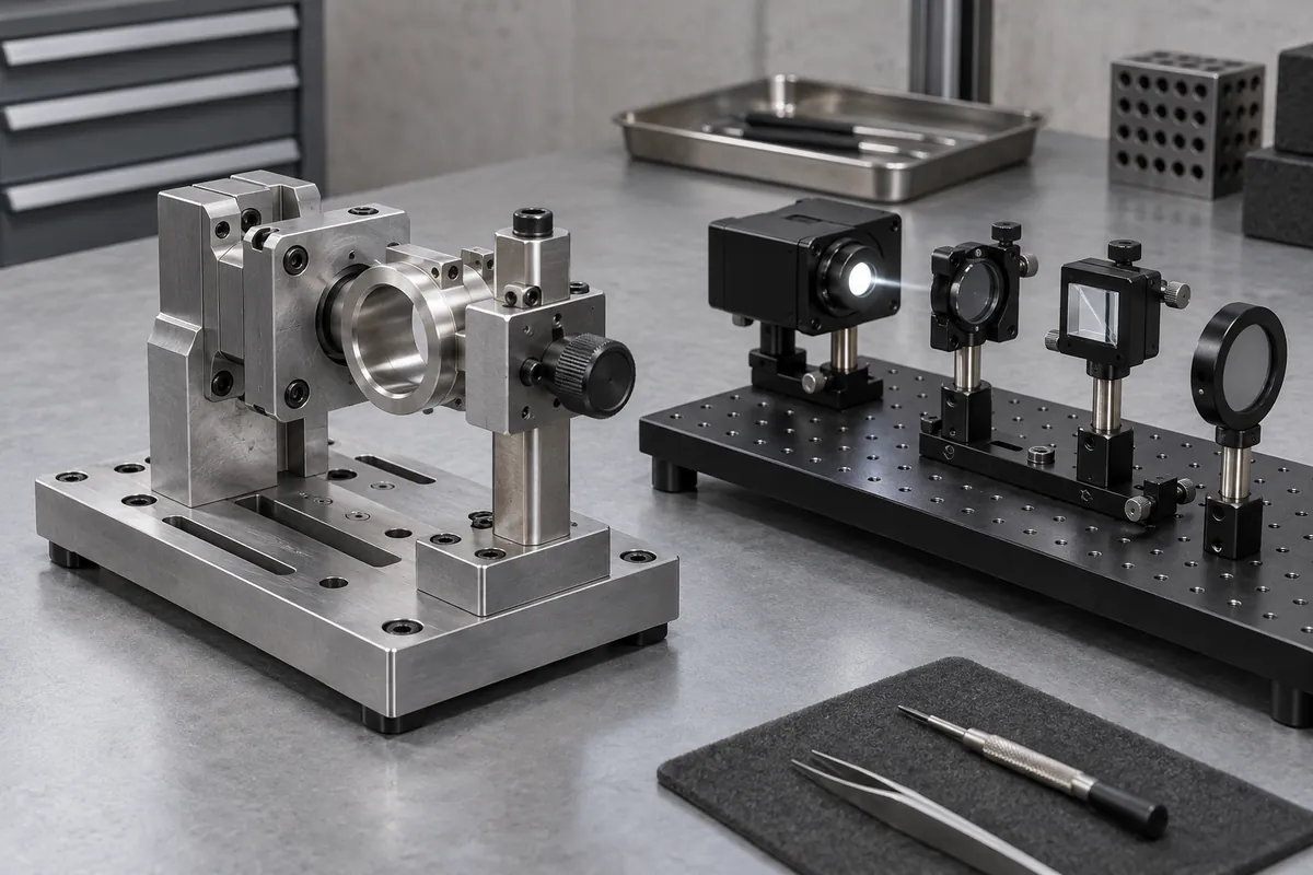
Product design illustrations. Final geometry, materials and acceptance criteria are project-specific.
An optical component report often combines mechanical dimensions, appearance and light measurements, but these results answer different questions. A good outside diameter does not prove the correct focal behavior, and a polished surface does not prove a specified form accuracy. A useful inspection plan assigns a method to each required outcome.
Begin with the optical design and assembled function. Identify the clear aperture, mounting references, relevant wavelength range and performance criteria. This lets the supplier distinguish ordinary dimensional checks from measurements that require specialized optical equipment or customer system validation.
Separate dimensions, form and surface condition
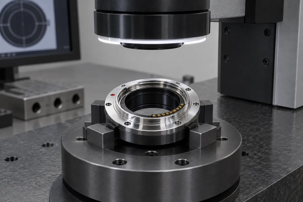
Diameter, thickness and locating features help control assembly. Their measurement should use defined datums and specimen support. For a flexible or thin molded optic, the fixture must not distort the component into an apparently acceptable condition that does not exist in the actual holder.
Surface form describes deviation from the intended shape under a defined measurement convention. A statement expressed as a fraction of a wavelength needs the wavelength, aperture and metric, such as PV or RMS, clearly identified. Do not publish a drawing target as a measured result when no corresponding report exists.
Edmund Optics' aspheric-lens guidance distinguishes form error and roughness. A mold-polish classification or a favorable visual observation is not a substitute for a surface-form measurement on the finished part.
Match the light measurement to the claim
Transmission and haze require their own specimen and collection conditions. A curved lens can redirect light differently from a flat material plaque, so the method must account for geometry. Keep material datasheet values separate from measurements actually made on the supplied component.
An integrating-sphere system can measure quantities such as total luminous flux under the appropriate setup. Gigahertz-Optik's instrument information describes these measurement applications. Total flux is not a map of the projected beam's spatial uniformity.
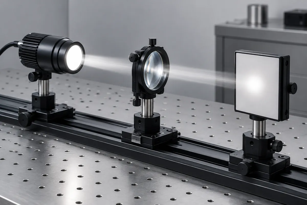
Beam distribution or target-plane uniformity needs an appropriate spatial measurement arrangement. Define source alignment, distance, detector and the evaluated region. A photograph of a bright spot can illustrate the setup but cannot replace a quantitative distribution measurement.
Control the source and the sample population
For an illumination assembly, identify the LED or other source configuration, drive condition and stabilization procedure. A change in source output can be mistaken for a lens difference. Compare specimens using a controlled setup and an explicitly defined reference.
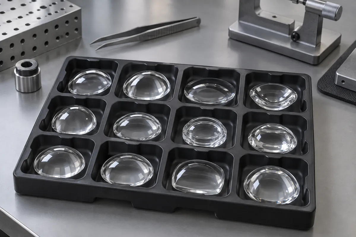
Sample across cavities where the tool produces multiple parts at once. Record cavity identity and report the actual number measured. A small first-article optical sample can support development without proving that every production lens received the same specialized inspection.
Separate first-article qualification from routine production checks. The former may use detailed optical metrology, while the latter uses an agreed combination of dimensions, appearance and sampled functional tests. State the distinction instead of implying that every shipped part was measured by every available instrument.
Define the comparison reference for any reported percentage difference between cavities or samples. A deviation from the batch mean, a reference lens or a nominal design output describes a different calculation. Retain the source conditions and individual readings so the summary can be checked. Without that definition, a claim such as plus or minus three percent can appear precise while remaining technically ambiguous.
Write a defensible release statement
List completed results with their method and sample scope, then identify any open requirements. If a form target lacks a retained report, leave it unverified rather than supplying a plausible-looking value. If an aging program is ongoing, keep its target separate from the completed exposure.
Connect the plan to cosmetic-zone inspection and the mounted configuration. A change to the holder, coating or source may require another system check even when the molded part drawing remains unchanged.
The result is a traceable chain from design requirement to measurement and release decision. It supports accurate purchasing and technical communication without turning unrelated favorable numbers into a blanket claim of optical precision or complete product qualification.
Discuss the component and its acceptance requirements
Explore our custom plastic optics and the related project case study. Send the current drawing, mating-part details, operating conditions and required quantities. We can review tooling, molding and inspection as a defined supply scope, with development samples and production approval kept separate.