
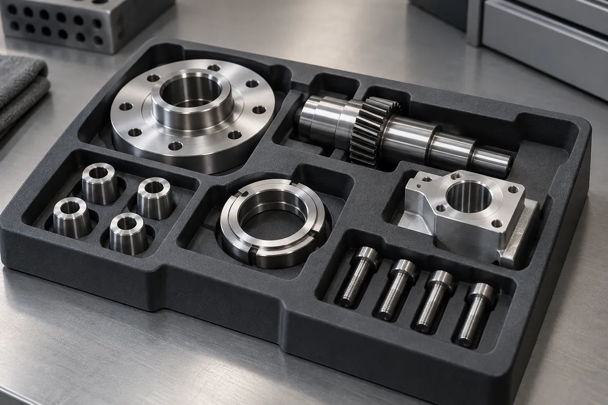
Product design illustrations. Final geometry, materials and acceptance criteria are project-specific.
A closely fitted pocket can look protective while making loading unreliable or damaging the part during removal. The goal is controlled support, not contact with every surface. Identify which features may carry load and which must remain untouched before turning the component model into a tray cavity.
Work from the component's production variation, not only its nominal CAD. Include the largest and smallest permitted envelopes, coatings, flexible features and the way the operator or gripper approaches the part. A tray needs clearance for that complete process, including any rotation required to extract the item.
Choose support points deliberately
Locate robust areas that can accept contact without cosmetic or functional damage. A shoulder, housing edge or mounting boss may be a better support than a polished face or projecting terminal. Draw these permitted zones explicitly so a later tooling change does not introduce an unintended contact point.
Provide relief around vulnerable features. Thin projections can be damaged even when the main component appears securely seated. Check movement under transport and stack loading, because a clearance that exists in an unloaded model may disappear when the tray base deflects or another component shifts.
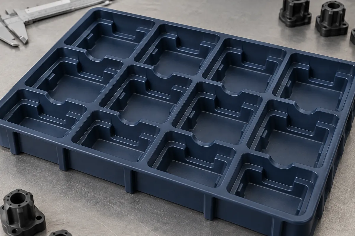
For injection molding, draft and wall transitions must remain compatible with release from the tool. Molding wall-thickness guidance provides a useful starting point for that review. It does not replace assessment of a particular deep pocket or support ledge.
Design the removal path as carefully as the pocket
Add access where fingers, vacuum cups or gripper jaws need to reach the part. An otherwise suitable pocket can fail because the tool cannot approach without contacting a neighboring wall. Review the full extraction path rather than a single gripper position above the seated component.
A vacuum pick may require a stable exposed surface and sufficient release from the pocket. A mechanical gripper may need side access and controlled part orientation. These approaches can drive different support features, so selecting the handling method after tray tooling is complete can create avoidable rework.
Consider whether a component can be loaded in the wrong orientation. Asymmetric locating details can discourage an incorrect placement, but they should not create sharp contact or excessive insertion force. Confirm that any poka-yoke feature remains effective across the component and tray tolerances.
Allocate clearance and retention
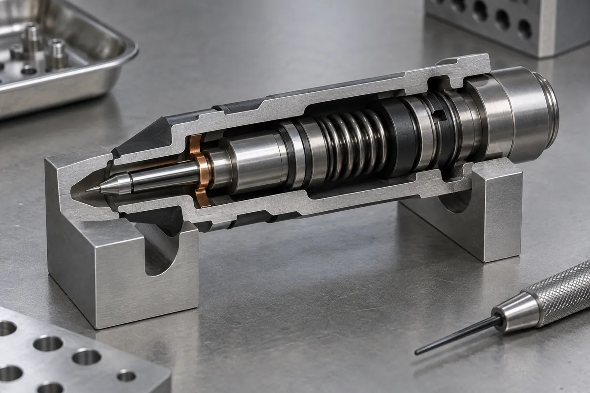
Separate location from retention. A pocket can establish an orientation while a lid or another feature prevents escape during transport. Trying to obtain both functions from an excessively tight cavity can create friction, abrasion or difficult release. State which handling events require positive retention.
Account for thermal change and the material behavior of both the component and tray. Clearance at inspection temperature may not be the clearance during a wash or a hot transfer. If a part is loaded soon after its own manufacturing process, include its actual condition in the handling review.
Do not specify every pocket dimension to the same tolerance. Identify the references controlling component location and the surfaces providing simple clearance. This lets the tooling and inspection plan concentrate on function rather than adding measurement effort to noncritical empty space.
Validate with representative parts and motion
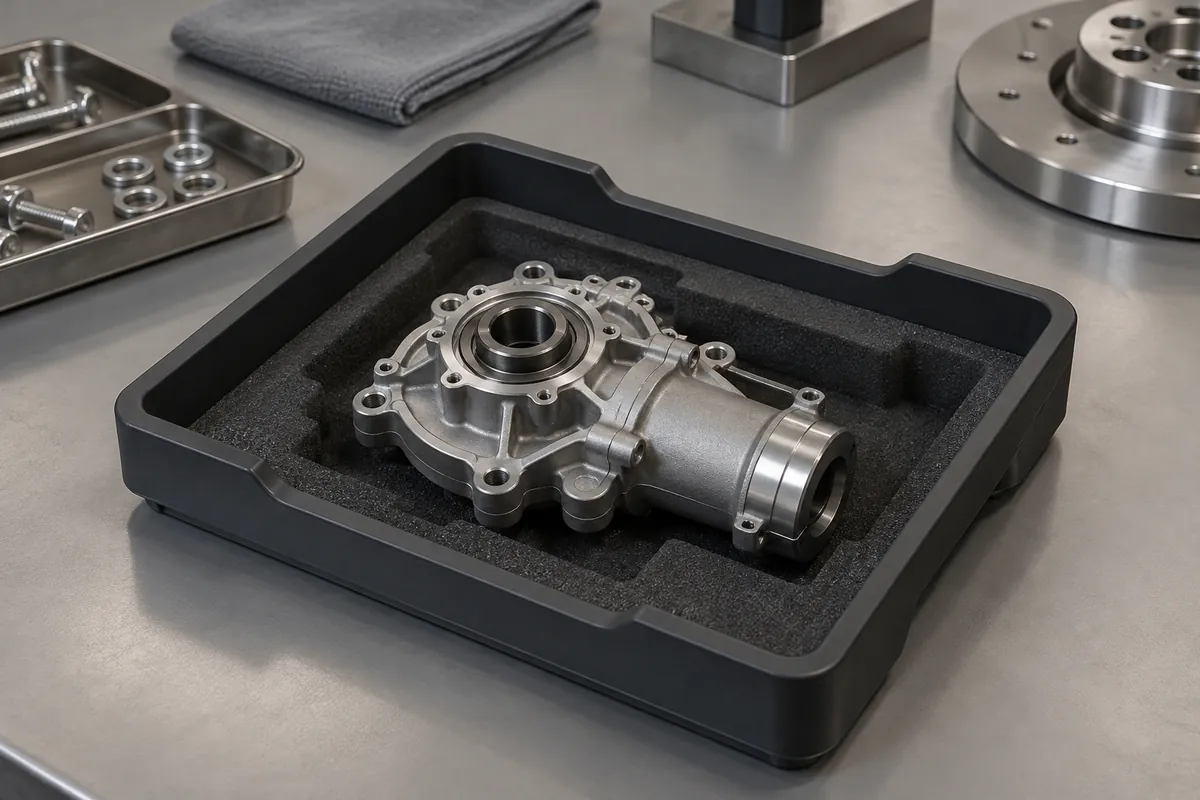
Test loading, seated stability and removal with identified samples at relevant tolerance conditions. Inspect the component afterward for damage, debris or marking. A successful tray dimension report does not establish that the carried product remains acceptable after repeated use.
Include worn trays when evaluating a returnable system. Support ledges and locating features can change through handling and cleaning. Define inspection or replacement criteria before wear causes an uncertain mixture of serviceable and unreliable carriers on the same line.
Coordinate this work with the robotic handling review. An approved pocket combines support, location, retention and release in a controlled sequence. Record the component revision and handling method with the tray approval so future changes can be evaluated against the same functional intent.
Discuss the component and its acceptance requirements
Explore our custom component trays and the related project case study. Send the current drawing, mating-part details, operating conditions and required quantities. We can review tooling, molding and inspection as a defined supply scope, with development samples and production approval kept separate.