
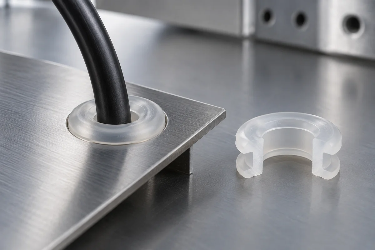
Product design illustrations. Final geometry, materials and acceptance criteria are project-specific.
A cable grommet can match the panel-hole diameter and still fit badly. The panel thickness, groove width, cable diameter and flange geometry determine how it seats after installation. When a seal is required, the relevant question is not simply whether the part can be pushed into the opening. It is whether the specified surfaces maintain the intended contact across the accepted assembly variation.
Start with a section through the installed assembly. Show the panel edge, grommet groove and cable jacket together. This makes it easier to distinguish dimensions measured on a free molded part from conditions created only after assembly. Confusing those two states can produce a drawing that looks precise but cannot be inspected consistently.
Give the panel opening a complete definition
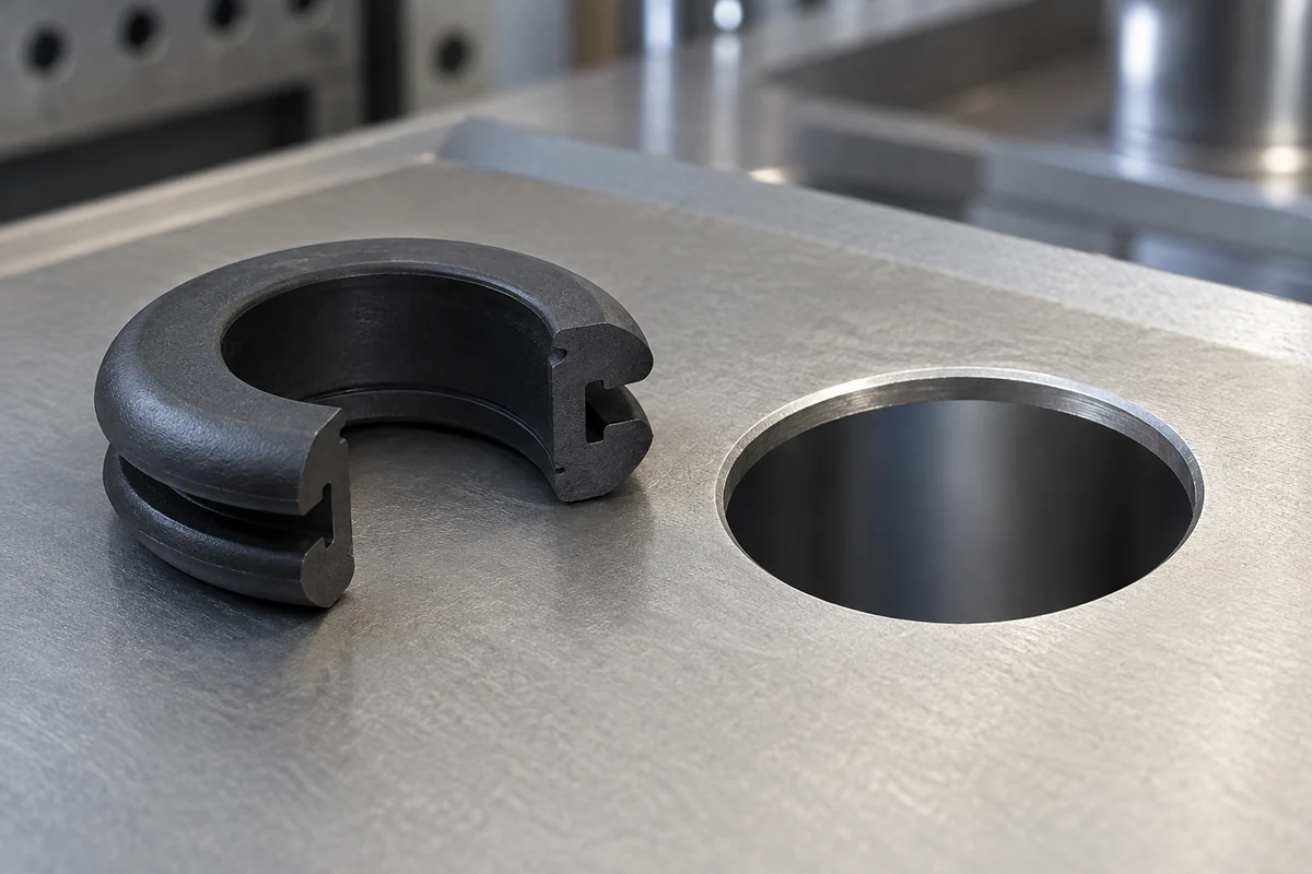
Specify hole size and tolerance, panel thickness and the relevant edge treatment. A sharp or damaged opening can cut a soft flange during insertion even when its diameter is correct. Coatings and formed edges also affect the final interface. Measure or specify the finished panel condition, not only the machining instruction before subsequent operations.
For a non-circular opening, identify the orientation features and local radii that control seating. The grommet may flex differently near a narrow end than along a broad side. An outline dimension alone cannot explain where contact is intended. Mark the functional surfaces and discuss where variation can be accepted without changing the installation method.
Match groove geometry to the finished panel
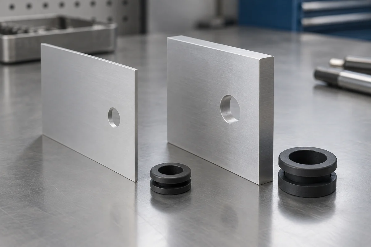
The groove is the space between the panel-retaining flanges. Its width interacts with panel thickness, while its depth and surrounding flange shape influence seating and resistance to displacement. Making it tighter is not automatically better: excessive deformation can roll a lip, prevent complete seating or create an unpredictable contact shape.
Review the thinnest and thickest accepted panels with the corresponding molded-part limits. Do not stack every tolerance as if it were an independent rigid clearance; the elastomer redistributes as it deforms. Use the tolerance review to identify assemblies for physical evaluation. It is a way to choose informative samples, not proof that a flexible interface will seal.
A flange may retain the grommet without being the main sealing lip. Document that distinction. If the design uses a dedicated raised lip, its local shape and seating reference deserve their own controls. Avoid applying a generic compression percentage taken from a different seal geometry. The contact arrangement and available deformation space need their own review.
Review the actual cable population
State the cable outside diameter, tolerance and jacket specification. Ovality, texture and jacket stiffness can affect the installed interface, so a smooth metal pin is not automatically an adequate substitute for the production cable. A pin can help measure a feature, but assembly validation should represent the cable configuration that the product actually uses.
Consider how the cable moves after installation. Side loading, bending or a nearby connector can change contact at the bore and panel groove. An enclosure that seals with an unloaded straight cable may behave differently when the harness is routed. Keep sealing and strain-relief requirements separate, then test the relevant combination where the application needs both.
Define interference before quoting a number
The word interference needs a named feature and measurement convention. Cable-to-bore interference, panel-to-groove fit and local lip compression describe different relationships. A diametral difference is not a radial compression value. Label the dimensions in a section and state the free-part or assembled condition before discussing an acceptable range.
For example, a drawing can list the cable diameter and free bore separately, then identify the assembly evaluation required at their limits. That is more useful than adding an unexplained instruction such as “tight fit.” Do not copy the dimensions of an unrelated successful project; the compound, contact length, panel and installation procedure may all differ.
Specify a measurement approach that does not distort the soft part beyond the agreed method. Optical inspection, section measurement and controlled contact methods answer different questions. Identify the support fixture, reference orientation and preparation of any destructive section. Repeated measurements have little meaning if each operator seats or compresses the sample differently.
Close the loop with installation and functional evidence
Inspect parts from identified cavities and evaluate them with controlled mating components. Record whether a lip folds during insertion, whether the part fully seats and whether the cable remains in the intended position. These observations often explain a failure more usefully than a single diameter measurement taken after the assembly has been disturbed.
Use the water-ingress test plan when sealing is part of the requirement, and review hardness and compression when selecting a compound. Dimensional approval, successful installation and functional acceptance should refer to the same drawing and component revisions. That connection is what makes a fit specification useful for repeat supply.
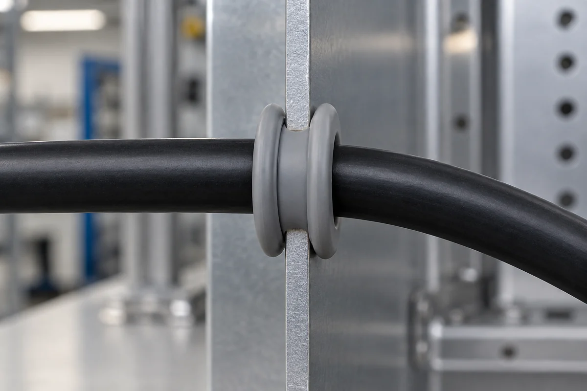
Review a defined cable-entry assembly
Explore our custom LSR silicone cable grommets and the cable-grommet pilot validation case study. Send the part drawing, panel and cable specifications, service conditions and acceptance plan to scope tooling, molding and inspection together.