
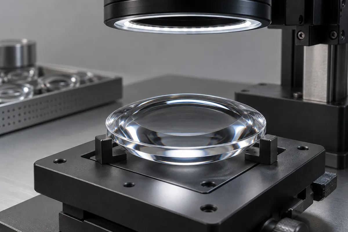
Product design illustrations. Final geometry, materials and acceptance criteria are project-specific.
Not every surface of a molded optic needs the same cosmetic requirement. A scratch across the working aperture can matter differently from a small mark on a concealed mounting tab. Defining zones makes inspection more meaningful and prevents cost from being added to surfaces that do not influence appearance or function.
Start with the assembled optical path and the customer's visible surfaces. Mark the clear aperture, mounting region and any secondary cosmetic area on the drawing. Then assign requirements that reflect the purpose of each zone instead of applying one unexplained scratch-and-dig label to the whole component.
Use a defined specification system
Scratch-and-dig notation belongs to a particular inspection convention; it is not a universal direct measurement of defect depth. Name the applicable standard or agreed procedure and edition where required. Otherwise, two suppliers may interpret the same numbers using different methods and reach incompatible acceptance decisions.
Edmund Optics' specification reference distinguishes surface quality from surface accuracy. That distinction is important: an acceptable cosmetic result does not establish that the optical surface has the required shape.
Where a formal optical standard is not appropriate, agree controlled visual criteria rather than borrowing technical-looking notation. Define defect types, zones and acceptance examples in a way the inspection team can apply consistently. The method should fit the actual application and available evidence.
Control the viewing condition
Lighting direction, background, viewing distance and magnification can change what an inspector sees. Specify the conditions relevant to the chosen method. A defect visible only under a different setup should not trigger an unplanned acceptance rule after production has already been approved.
Use clean, identified specimens and an agreed cleaning method. Dust or residue can be mistaken for permanent damage, while aggressive cleaning can create new marks. The inspection procedure should distinguish removable contamination from scratches, pits or internal inclusions.
Reference samples can help align judgments, but they need control. Record their revision and intended use, protect them from deterioration and avoid treating one sample as permission for every defect of vaguely similar appearance. Written boundaries remain useful even when comparison samples are supplied.
Connect defects to the manufacturing route
Record where defects occur and whether they repeat by cavity or handling stage. A recurring mark may originate in the tool, while random scratches may arise during transfer or packaging. This distinction helps target corrective work without automatically changing the molding process.
Review gates, parting lines and ejection contacts alongside the cosmetic zones. These features may have unavoidable residual characteristics that need explicit acceptance criteria. A general high-polish requirement does not explain how the gate edge or hidden mounting face should be judged.
Include packaging and receiving inspection. Optical surfaces can be damaged after an acceptable factory inspection if parts contact one another or unsuitable packing materials. Define separation and handling requirements that preserve the approved condition through the delivery route.
Agree how borderline findings will be reviewed before a shipment is held or accepted. A controlled escalation method using the same viewing setup and reference criteria is more useful than repeated subjective inspections under changing lights. Record the decision so similar findings receive consistent treatment across cavities, lots and receiving locations.
Keep optical performance separate
A surface can look good and still fail a form, transmission or system-performance requirement. Conversely, a cosmetic defect may have little functional effect but remain unacceptable in a visible consumer-facing zone. Keep those decisions explicit rather than using appearance as a proxy for every optical property.
Review the full inspection plan and identify the method supporting each claim. A mirror-polish designation on the tool does not establish a measured wavefront or surface-form accuracy for the molded production part.
Release the zones, methods and acceptance references with the component drawing. If the customer's viewing conditions or optical aperture change, revisit the criteria. A precise and proportionate appearance specification is more useful than an absolute defect-free promise that cannot be measured consistently.
Discuss the component and its acceptance requirements
Explore our custom plastic optics and the related project case study. Send the current drawing, mating-part details, operating conditions and required quantities. We can review tooling, molding and inspection as a defined supply scope, with development samples and production approval kept separate.