
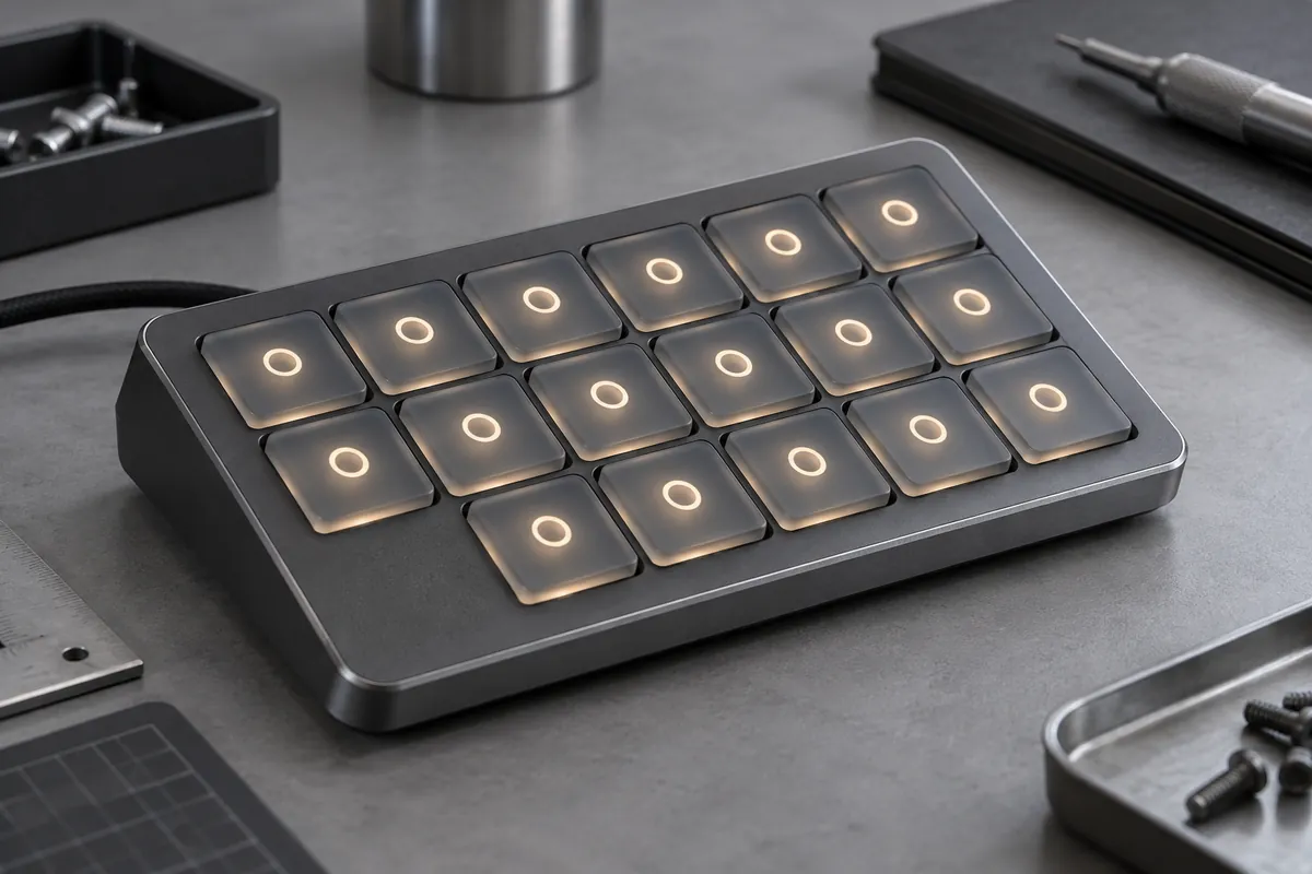
Product design illustrations. Final geometry, materials and acceptance criteria are project-specific.
A translucent silicone key does not guarantee a readable backlit interface. Light must reach the intended legend without illuminating neighboring keys, revealing unwanted hot spots or reducing contrast in daylight. The LED position, key construction, coating and surrounding bezel all participate in that result.
Treat the light path as an assembly feature. A molding quotation can cover the keymat and a defined decoration process, but the finished appearance depends on electronics and housing details that may be outside that supply scope. Share those interfaces early so the cosmetic target is physically meaningful.
Define where light should emerge
Mark illuminated regions and areas that must remain dark. Include the viewing direction, surrounding ambient light and the intended operating brightness. A tiny illuminated symbol viewed straight on presents a different problem from a broad legend that must remain legible at an oblique angle.
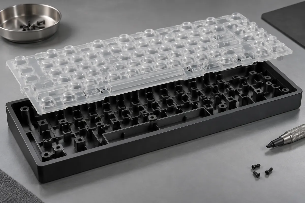
Choose a construction that supports those zones. Possibilities include translucent silicone beneath an opaque layer, separately controlled light-transmitting regions or additional light barriers in the housing. These choices affect decoration, tooling and assembly. Do not assume that changing pigment alone will solve light spreading across a connected keymat.
A keypad manufacturer's laser-marking overview illustrates the connection between surface decoration and backlighting. A specific proprietary process is not implied here; define the actual layer structure and removal or marking method in the purchase specification.
Control hot spots and light leakage
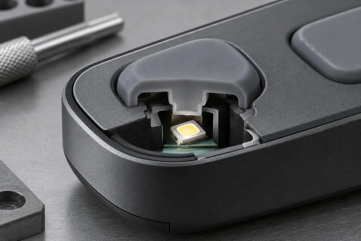
Review the LED-to-key distance and the space available for light distribution. A source close to a transmitting surface can create a localized bright region. More separation or a suitable optical treatment may help, but the available envelope and efficiency requirements constrain the solution.
Inspect the spaces between keys and around the perimeter. A barrier that works in a free-standing sample may leave a gap after tolerance variation or fastening. Conversely, an oversized barrier can touch a moving web and change tactile response. Optical isolation and mechanical clearance need to be reviewed together.
Keep neighboring-key conditions in the test plan. Photographing one illuminated key with all other sources off does not establish the behavior when the whole panel is active. Compare the required operating combinations, including any dimming settings that could make low-level leakage particularly noticeable.
Specify appearance in measurable terms
Provide an approved reference sample or a controlled visual inspection setup. Define the viewing distance, angle, ambient light and electrical drive condition. If luminance or color variation matters, identify the instrument and measurement locations. The word uniform leaves too much room for different interpretations.
Distinguish cosmetic acceptance from electrical power settings. Increasing LED current can hide a dim region while creating heat, glare or a stronger hot spot elsewhere. A mold or coating adjustment should be evaluated against the original electrical condition so the comparison remains useful.
Repeat the relevant checks after the agreed cleaning, abrasion or aging exposure. Decoration damage may create unwanted light windows before the key stops functioning electrically. Functional switching and visual durability therefore need separate acceptance observations and clear records of the tested finished state.
For a multicolor panel, include the required source colors in the sample approval. A silicone thickness or pigment that distributes one color acceptably may not provide the same appearance with another source spectrum. Keep the optical samples and their drive settings together so a later electronics change triggers a meaningful review of the original acceptance.
Keep optical and sealing claims separate
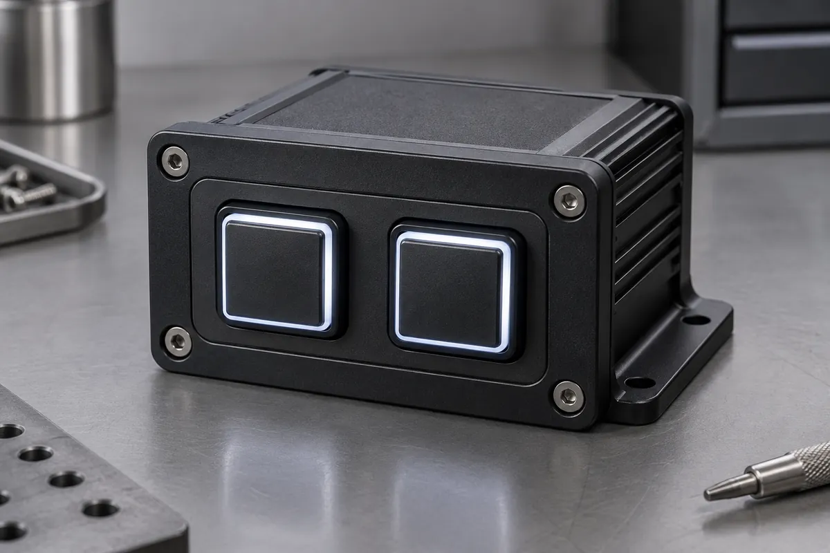
An opaque perimeter or molded lip does not establish an ingress-protection rating. Sealing requires the intended assembly, loading and test method. Likewise, a backlighting trial does not establish suitability for every cleaning chemical used in a clinical or industrial environment.
Compare printed and laser-etched legend processes before finalizing the cosmetic drawing. Release the approved light path, decoration stack, drive conditions and viewing criteria together. This makes future material or supplier changes reviewable instead of relying on an informal judgment that the replacement looks close enough.
Discuss the component and its acceptance requirements
Explore our custom silicone keypads and the related project case study. Send the current drawing, mating-part details, operating conditions and required quantities. We can review tooling, molding and inspection as a defined supply scope, with development samples and production approval kept separate.