
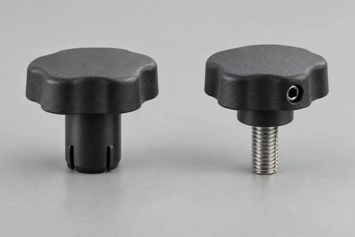
Product design illustrations. Final geometry, materials and acceptance criteria are project-specific.
A push-on knob can simplify assembly, while a set-screw design can provide an adjustable fastening method. Neither description is enough to choose a design. The shaft, operating torque, service needs and allowable assembly forces determine whether the proposed arrangement is appropriate.
For a custom injection-molded knob, compare complete assemblies rather than bare plastic shapes. A lower part price may exclude an insert, screw, installation tool or additional inspection step that the other proposal includes. Define the delivered configuration before evaluating cost.
Understand what a push-on design relies on
A push-on interface may use controlled interference, a compliant feature or another specified retention element. Describe the actual mechanism instead of using press-fit as a catch-all term. The bore and shaft definitions, materials and engagement length belong in the same specification.
Agree how installation force will be applied and reacted. The load should follow an approved assembly path, especially where the shaft belongs to a purchased control component. A successful hand assembly on a loose shaft does not demonstrate suitability for the installed control.
Define the seating position and inspect for unintended bottoming. If the knob contacts the panel before the intended engagement is reached, the apparent assembly force can be misleading. Panel gap and shaft engagement should be checked separately.
Account for the complete set-screw joint
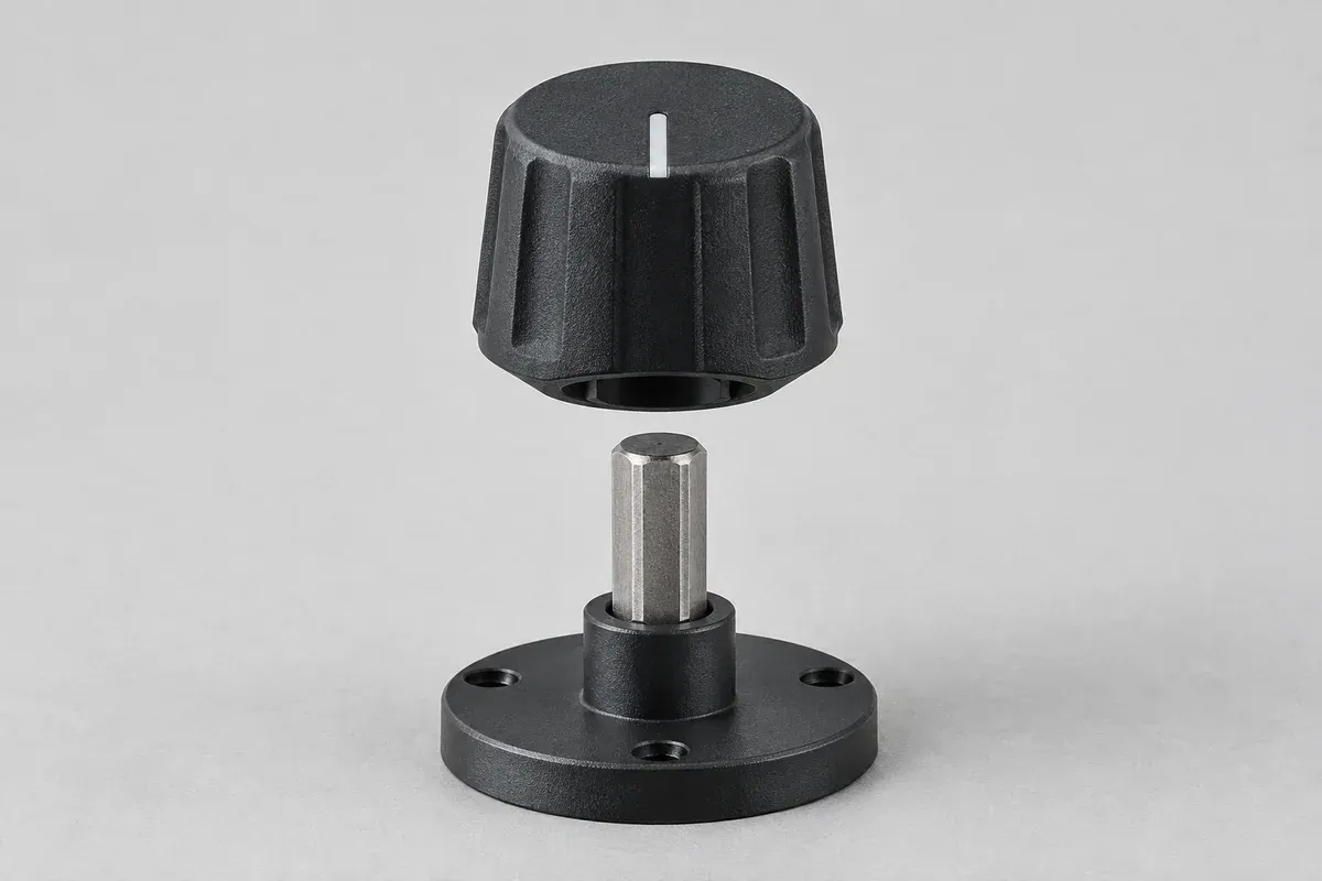
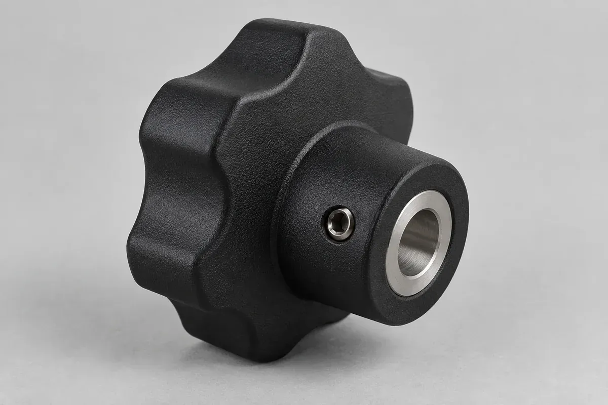
A set screw introduces a threaded joint, local load and a service-access requirement. State the screw specification, thread location, mating shaft feature and tightening method. If a metal insert carries the thread, its retention in the plastic also needs a defined design and acceptance plan.
The screw should remain accessible in the actual panel arrangement. A surrounding recess or adjacent control can make a workable bench assembly impractical in the finished product. Check tool access through the full installation and removal sequence.
Consider whether repeated adjustment or removal is required. That use case can affect the selected joint and inspection plan. Do not assume that a one-time successful tightening operation demonstrates acceptable repeated service behavior.
Compare angular control and shaft condition
Both approaches need a deliberate relationship between the shaft and the visible index. A set screw on a round shaft may allow angular adjustment, but the method for setting and maintaining that position must be defined. A keyed interface has its own dimensional and orientation requirements.
Ask whether marks or deformation on the shaft are permitted. The answer belongs to the assembly designer or control manufacturer. A fastening method that secures the knob but damages a prohibited surface is not an acceptable solution.
Use the shaft-interface guide to collect the counterpart definition. Do not adapt a stock mounting assumption to a custom shaft without checking the actual geometry and operating requirements.
Test the requirements independently
Installation force, operating torque and axial retention are different measurements. Define the relevant conditions and acceptance criteria for each. A high pull-off force does not demonstrate correct angular indication, and an easy installation does not establish reliable retention.
Where environmental or repeated-use testing is required, describe it in the approval plan. The selected resin, counterpart material and service conditions determine the questions. Avoid assigning a universal load or cycle rating from the mounting-method name alone.
The knob acceptance guide discusses fixtures, specimen identity and reporting. Keep any destructive evaluation separate from parts intended for subsequent assembly unless the test plan explicitly permits their continued use.
Release a mounting method with clear ownership
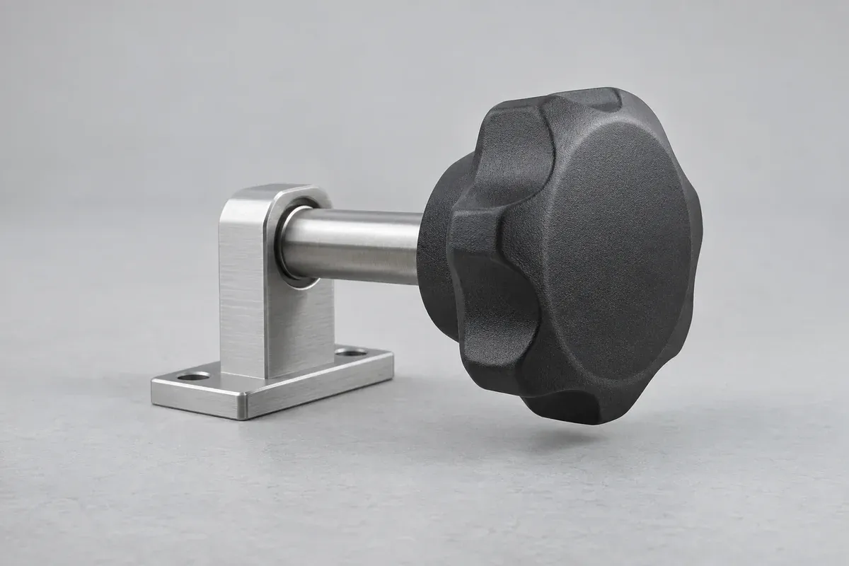
List the supplied hardware, installation instructions, required checks and responsibility for the mating shaft. State whether the molding supplier provides a complete knob assembly or only the plastic body. This avoids a gap between component acceptance and final fastening.
Compare the expected assembly effort, service access and change-control requirements alongside tooling and piece price. A design that removes one assembly step may add a tighter interface-control obligation elsewhere. Make that trade-off visible in the decision.
The outcome should be a documented mounting arrangement that fits the actual product. It should not be a blanket claim that push-on knobs are always faster or set-screw knobs always stronger. Those conclusions require evidence from the defined configuration and process.
Turn the review into a defined molding scope
Explore our custom injection-molded control knobs and the related illustrative engineering study. Send the drawing revision, counterpart details, intended use and the decisions still open. Development samples and production approval should have separate, agreed deliverables.