
Custom molded parts · Made to your design
Custom Injection-Molded Electronic Enclosures
An enclosure designed around your board, connectors and assembly—not just an outside box dimension.
Request custom molded housing bases, lids and bezels made to an agreed design. Bring the populated PCB envelope, mating interfaces and intended use into one DFM review, from material selection and tooling through identified samples and production approval.
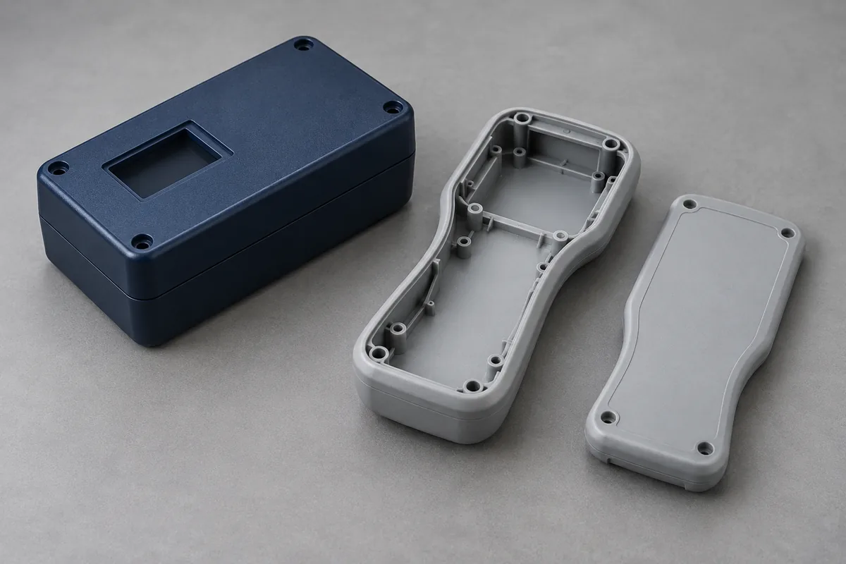
Product details
Explore the enclosure details that control assembly
See exterior and interior design examples, with closer views of board supports, connector openings, perimeter fit and cosmetic surfaces.
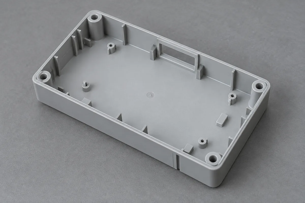
Housing base
Review internal space and functional features with the populated board and the matching lid.
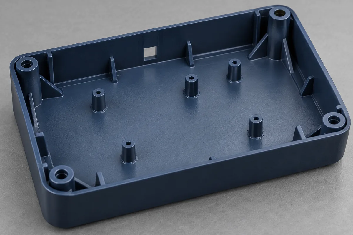
PCB supports and bosses
Define support, location and retention separately; they do not all need the same fit.
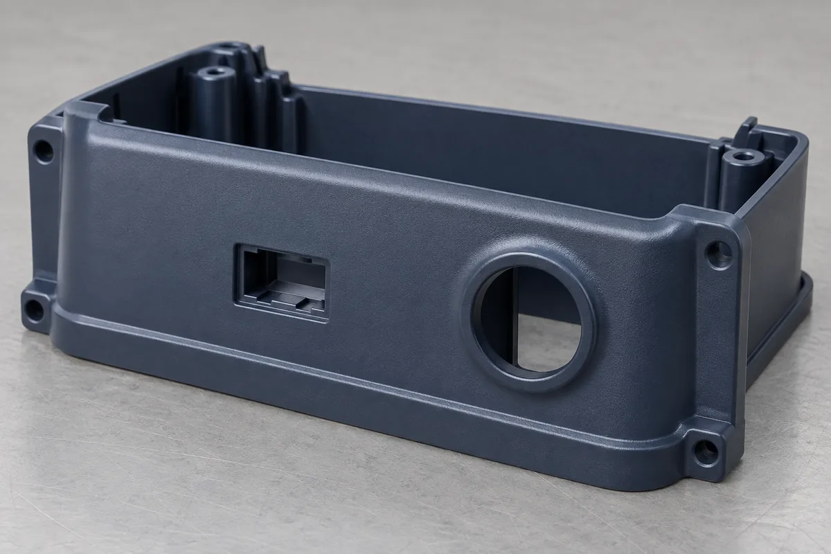
Connector and cable openings
Include the connector, mating plug and insertion path in the opening review.
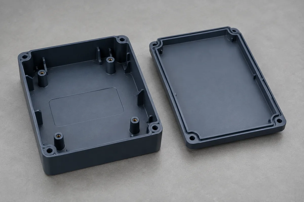
Lid and locating rim
Agree mating clearance, seam gap and flushness before evaluating the assembled pair.
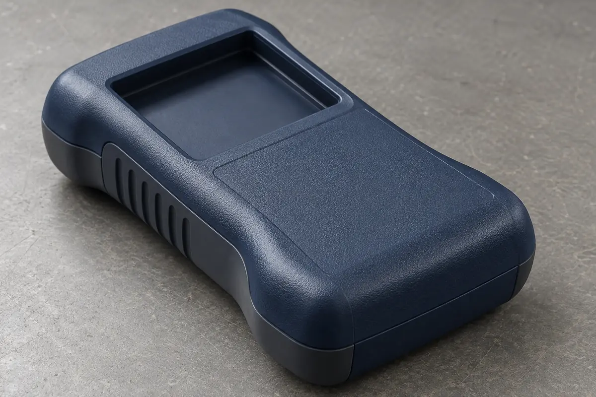
Visible surface detail
Specify appearance zones, texture boundaries, color and permitted molding witnesses.
Illustrative configurations. Final specifications follow your approved drawings.
Application fit
Custom housing parts for a defined electronic assembly
The illustrations show manufacturing applications, not catalog stock or completed customer devices. Your drawing and interface requirements define the delivered parts.
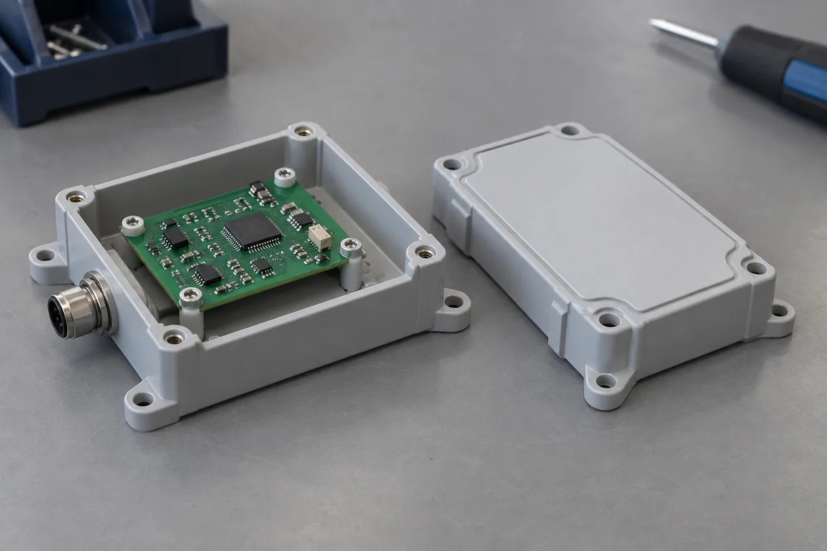
Sensor and monitoring housings
Bases and covers with project-specific board supports, connector windows and mounting features. Review the installation environment and counterpart geometry together.
Handheld instrument enclosures
Housing halves and bezels with a defined grip envelope, display interface, fastening method and visible-surface requirements.
Control and interface covers
Custom covers and front panels that locate switches, displays or connectors. Identify the functional openings separately from decorative recesses.
Quote-ready inputs
What to send for a meaningful quotation
Use the same drawing and requirements for every proposal. Mark open decisions explicitly so that a low price does not conceal a different deliverable.
| Area | Please provide | Review before release |
|---|---|---|
| Part and assembly geometry | Base, lid and bezel CAD/drawings; populated PCB and mating-component envelopes. | Controlled revisions, no-change interfaces and the governing document. |
| Material and environment | Approved grade if selected, color, heat, impact, cleaning and outdoor exposure. | ABS, PC/ABS or other candidates screened against the actual requirements. |
| Location and fastening | Support and locating scheme, screw/insert details, engagement and service access. | Separate board position, lid closure and joint-retention requirements. |
| Appearance | Visible zones, texture, color reference and permitted gate or parting-line locations. | Representative molded samples and reproducible acceptance conditions. |
| Inspection and qualification | Critical features, datums, specimen state, functional checks and required reports. | Component inspection separated from finished-device testing and its owner. |
| Order and tooling scope | Trial quantity, initial order, repeat demand, packing, destination and timing. | Tooling ownership, sample approval, production release and change control. |
From drawing to approval
From enclosure drawing to an approved molded configuration
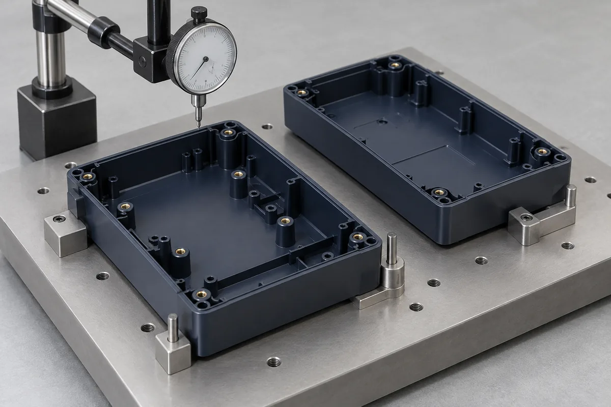
Review the interfaces
Confirm the PCB, connector, cover and fastening revisions. Identify open assumptions and which geometry can change during DFM.
Define material and tooling
Review exact resin candidates, wall transitions, draft, gate, ejection and appearance constraints before the tooling scope is approved.
Evaluate identified samples
Check the agreed dimensions, empty-housing fit and representative assembly. Record material, cavity, specimen condition and any approved deviations.
Release and control changes
Approve the configuration and its evidence package. Keep resin substitutions, tool changes and assembly revisions subject to the agreed review.
Practical engineering and buying guides
Six decisions to make before production
- Stock vs Custom Injection-Molded Enclosures: When to SwitchCompare modified stock enclosures with custom injection molding using assembly fit, tooling cost, design stability and realistic production demand.
- ABS vs PC/ABS for Electronic Enclosures: A Selection GuideChoose ABS or PC/ABS for a molded electronic housing by comparing exact grades, heat, impact, cleaning exposure, finish and assembly requirements.
- PCB Locating Posts and Connector Openings: Fit ChecksReview PCB support height, locating features and connector openings as one enclosure tolerance chain. Separate retention from location and clearance.
- Plastic Enclosure Screw Bosses: Cracking and Sink MarksDiagnose cracked enclosure screw bosses and visible sink separately. Review pilot holes, fasteners, local wall mass, molding history and acceptance.
- Molded Enclosure Appearance: A Cosmetic Acceptance PlanDefine visible zones, texture, color, gate marks and viewing conditions for molded electronic enclosures before approving tooling and samples.
- Uneven Plastic Enclosure Lid Gaps: Warpage and Fit ChecksDiagnose uneven enclosure lid gaps by separating free-state warpage, locating-lip interference, internal stack height and fastening effects.
Before you request a quote
Do you sell standard off-the-shelf electronic boxes?
This page is for custom injection-molded enclosure parts made to an agreed design. If a stock box with simple modifications suits your requirement, compare that route before investing in dedicated tooling.
Should my enclosure use ABS or PC/ABS?
The exact grade depends on heat, impact, cleaning, appearance and assembly requirements. Send the application brief and any required material documentation; a family name alone is not an approval.
Can the housing include board supports and connector openings?
Yes, these features can be considered in the custom design. Their geometry, mold release, tolerance relationships and mating components must be reviewed before tooling.
Is the enclosure automatically waterproof or electrically certified?
No. Any ingress, electrical, EMC or other finished-product claim requires the applicable evaluation of the actual assembly. Those responsibilities and tests must be explicitly scoped.
Can you quote before every design detail is final?
An initial discussion can identify assumptions and alternatives, but a production tooling release requires controlled drawings and closed critical interfaces. Mark unresolved decisions in the RFQ.
What images and files help the first review?
Send neutral 3D CAD, dimensioned drawings, populated-board and counterpart details, and photographs of any existing fit problem. Include resin, quantities and the checks needed for approval.
Your next step
Discuss the part with its intended function.
Send the enclosure drawing with its PCB, connector and mating-cover information. We can discuss a project-specific molding scope that keeps material, appearance and assembly acceptance aligned.
Explore our injection molding service or review other custom molded applications.