
Custom molded parts · Made to your design
Custom Injection-Molded Clips and Retainers
Bring the clip, its mating part and its required function into one manufacturing review.
Request custom plastic panel clips, component retainers or integral snap-fit features with project-specific resin, tooling, inspection and production scope.
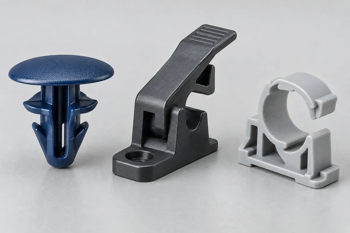
Product details
A closer look at the clip
Explore the mounting interface, flexible arm, root transition and engagement features.
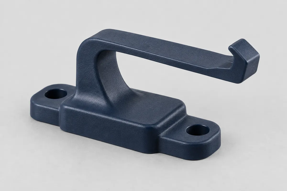
Clip geometry
The mounting base, flexible arm and engagement hook form the core of the clip geometry.
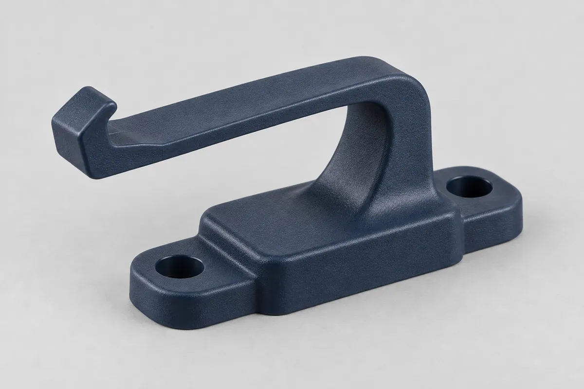
Mounting interface
Review the mounting interface and the space available around the arm.
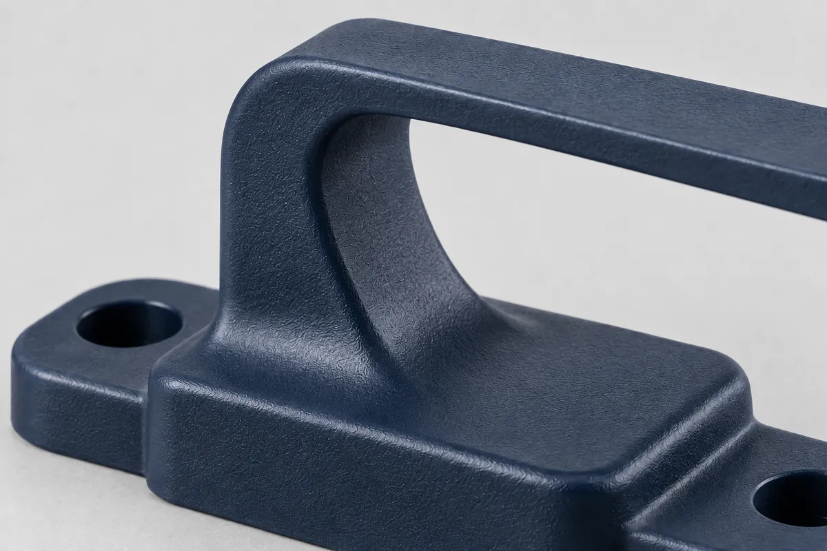
Cantilever root
The root transition and surrounding clearance belong in the design review.
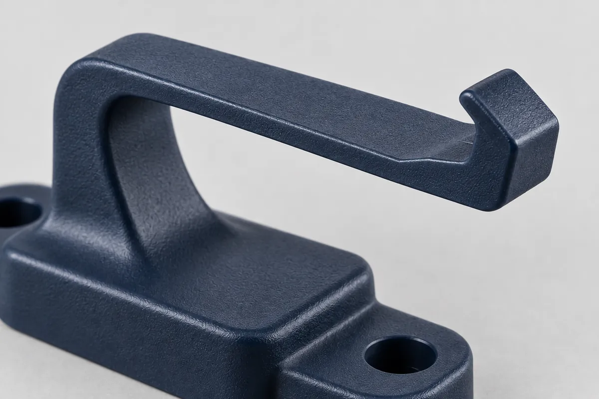
Hook & release tab
Look at the lead-in, retaining face and access for deliberate release.
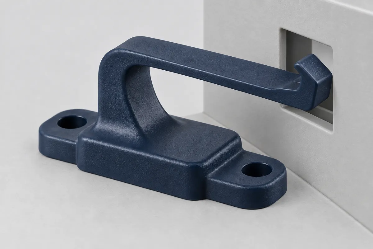
Panel engagement
Review the receiving opening, engagement depth and release access together.
Illustrative configurations. Final specifications follow your approved drawings.
Application fit
Small parts. Important assembly decisions.
A clip can locate a panel, retain a component or allow a cover to be removed for service. Those functions need different geometry and acceptance checks. The quotation starts with your assembly, not a generic promise that every clip will behave the same way.
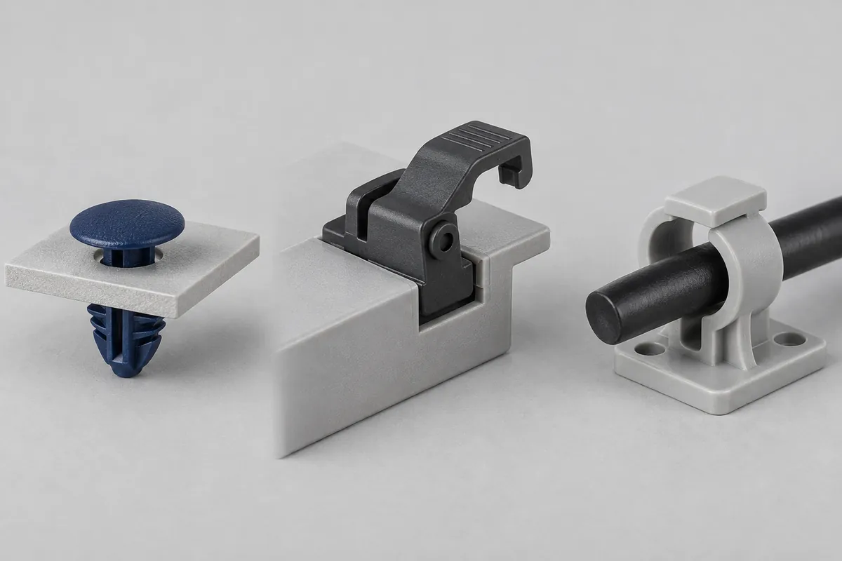
Panel and component clips
Define the receiving opening, panel thickness, allowed movement and required engagement. Include the counterpart drawing so the interface can be reviewed.
Removable cover latches
Show the insertion and deliberate release sequence, access to the tab and the space available for the flexible arm to move.
Cable and part retainers
Identify the retained geometry, load direction and exposure. Distinguish a locating function from a load-bearing or continuous clamping requirement.
Quote-ready inputs
Specify the function alongside the drawing.
If an input is not settled, say so. An open decision is easier to review than an assumption hidden inside a unit price.
| Area | Please provide | Review before approval |
|---|---|---|
| Part and counterpart | 3D CAD, dimensioned drawings, revisions, receiving window or panel, and surrounding assembly. | Engagement, access, tolerance combinations, support and any permitted design changes. |
| Material and environment | Approved resin grade if selected; reinforcement, color, temperature, moisture and relevant chemical exposure. | Candidate material scope and the evidence needed for the actual use condition. |
| Assembly and release | Insertion path, intended release action, one-time or reusable use, and access restrictions. | Beam geometry, root transition, deflection clearance and manufacturing release route. |
| Retained function | Required engagement, loading directions, sustained loads and any clamping or anti-rattle function. | Separate criteria for initial assembly, long-term retention and repeated operation. |
| Acceptance evidence | Critical features, inspection method, test owner, sampling and required records. | Trial approval, fixtures, testing responsibility and separately quoted activities. |
| Order and tooling scope | Trial quantity, initial order, repeat demand, timing and tooling ownership requirements. | Tooling proposal, development assumptions, approval hold points and production quotation. |
Material selection and beam design should be reviewed together. See the unfilled versus glass-filled resin comparison and cantilever clip design review for the questions that change a proposal.
From concept to release
Agree the evidence before ordering production.
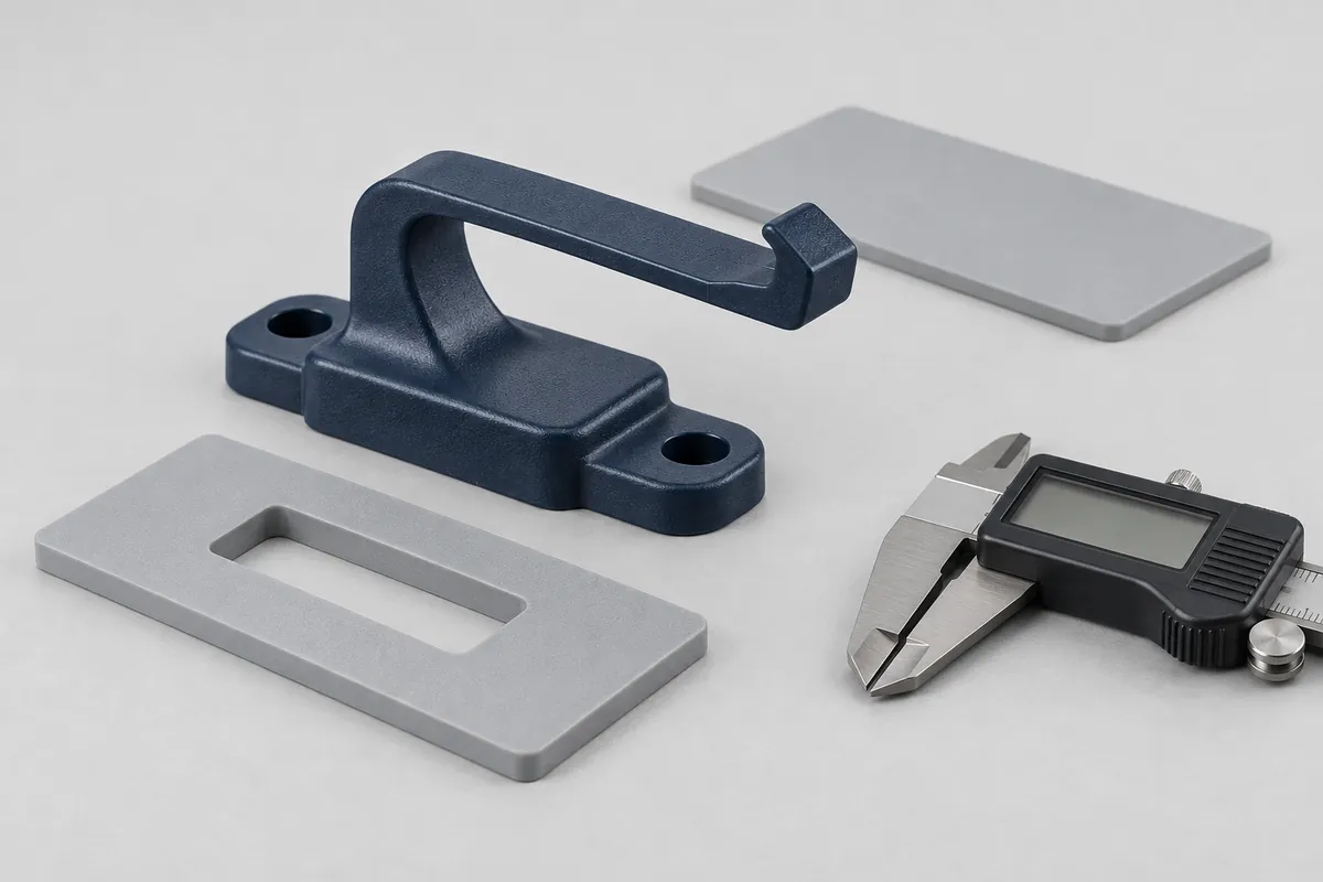
Review the assembly
Confirm the two mating parts, use sequence, environment and requirements that must remain fixed.
Resolve manufacturing
Review resin, gate, undercut release, tool construction and any controlled geometry changes.
Assess trial samples
Use identified samples for the inspection and functional checks included in the agreed scope.
Release the configuration
Close open actions and record the approved drawing, material, process and change-control requirements.
Six focused decisions
Practical guides for your clip program
- Cantilever Snap-Fit Clips: A Design Review for Molded PartsReview cantilever snap-fit geometry, engagement, root strain, assembly access and release requirements before quoting a custom injection-molded clip.
- Plastic Clip Retention Under Sustained Load: Planning for CreepDistinguish creep from stress relaxation in plastic clips and define exposure, support, retained engagement and post-aging force checks before approval.
- Snap-Fit Cycle Testing: Insertion Force, Removal Force and Failure RecordsDefine a snap-fit cycle test with controlled fixtures, insertion and release actions, specimen conditioning, force records and project-specific acceptance.
- Unfilled vs Glass-Filled Resin for Flexible Clips: A Selection ChecklistCompare unfilled and glass-filled resin grades for flexible molded clips using deformation needs, material condition, flow orientation and validation scope.
- Gate and Weld-Line Review for Load-Bearing Snap-Fit ClipsCompare gate concepts for molded snap-fit clips, mapping likely flow splits against the beam root, contact surfaces and required validation evidence.
- Releasing Undercuts in Plastic Clips: Flexing vs Side-Action ToolingCompare flex-release and side-action tooling for a molded clip undercut, including clearance, release geometry, material limits, damage checks and quote scope.
Before you send a clip RFQ
Do you sell stock automotive trim clips or replacement fasteners?
This page describes custom injection-molded parts made to an agreed design, not a stock fastener catalog. Include your part and mating drawings for a project-specific quotation.
Can the clip be molded as part of a housing?
An integral latch and a separately molded retainer are both application concepts to review. The geometry, assembly, material and tooling proposal determine the appropriate scope; integration is not automatically better.
Which material is best for a flexible snap-fit?
There is no universal choice. The required displacement, retained function, exposure, cycle requirements and exact grade data need to be considered together. A high tensile-strength value alone does not establish clip suitability.
Can you guarantee a removal force or number of cycles?
Only project-specific requirements supported by an agreed method and relevant validation can define acceptance. This page assigns no generic force, cycle life or load rating.
Does every clip need side-action tooling?
No. The actual undercut and release path need review. A flex-release proposal must justify the geometry and material condition; a side-action proposal must show its travel and opening sequence.
What should I send before requesting a quote?
Send CAD and drawings for the clip and mating part, intended assembly/release sequence, grade if selected, service environment, quantities and acceptance requirements. Mark unresolved inputs as open decisions.
Your next step
Send the clip and the part it engages.
Include drawing revisions, resin if selected, assembly access, service conditions, trial and production quantities, and the evidence needed for approval. We can then discuss a defined injection-molding scope rather than an isolated part price.