
Custom molded parts · Made to your design
Custom Injection-Molded Plastic Spacers and Standoffs
Control the distance between parts with a spacer designed around the complete assembly.
Send your spacer drawing with its mating components, exact material requirements and expected quantities. FECISION reviews custom injection molding, sample inspection and recurring supply. These parts are made to an agreed design, not offered as interchangeable stock hardware.
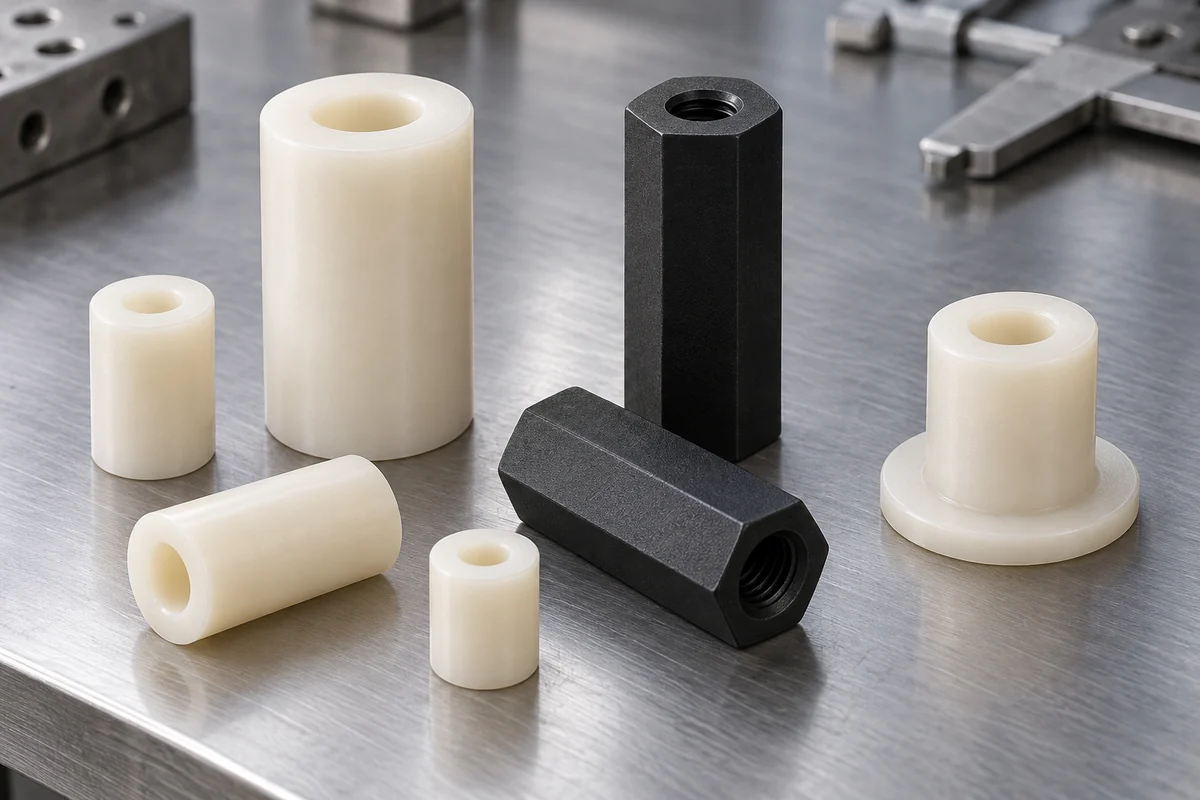
Product details
Explore the features that establish spacing and fit
Product design illustrations show alternative support forms. Final geometry, material and acceptance criteria are project-specific.
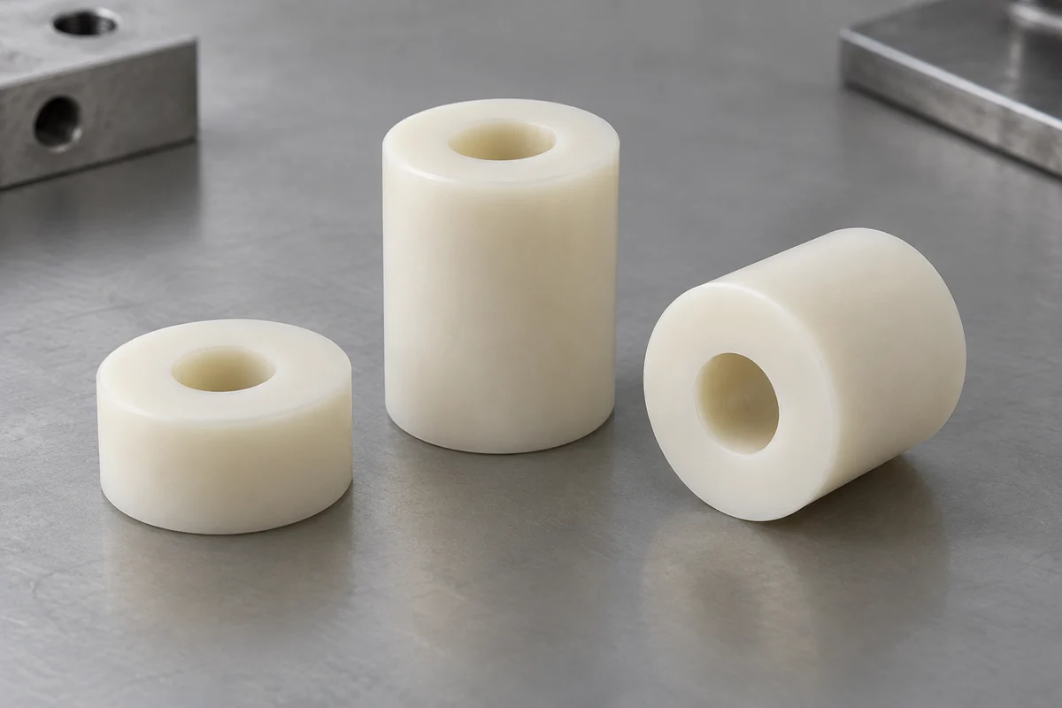
Through-bore sleeve
Define bearing-face height and through-fastener clearance separately.
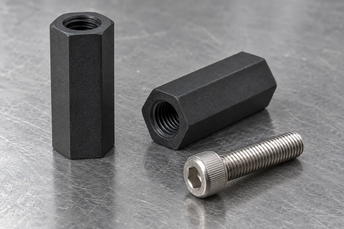
Threaded standoff
Specify thread engagement and validate the complete fastened connection.
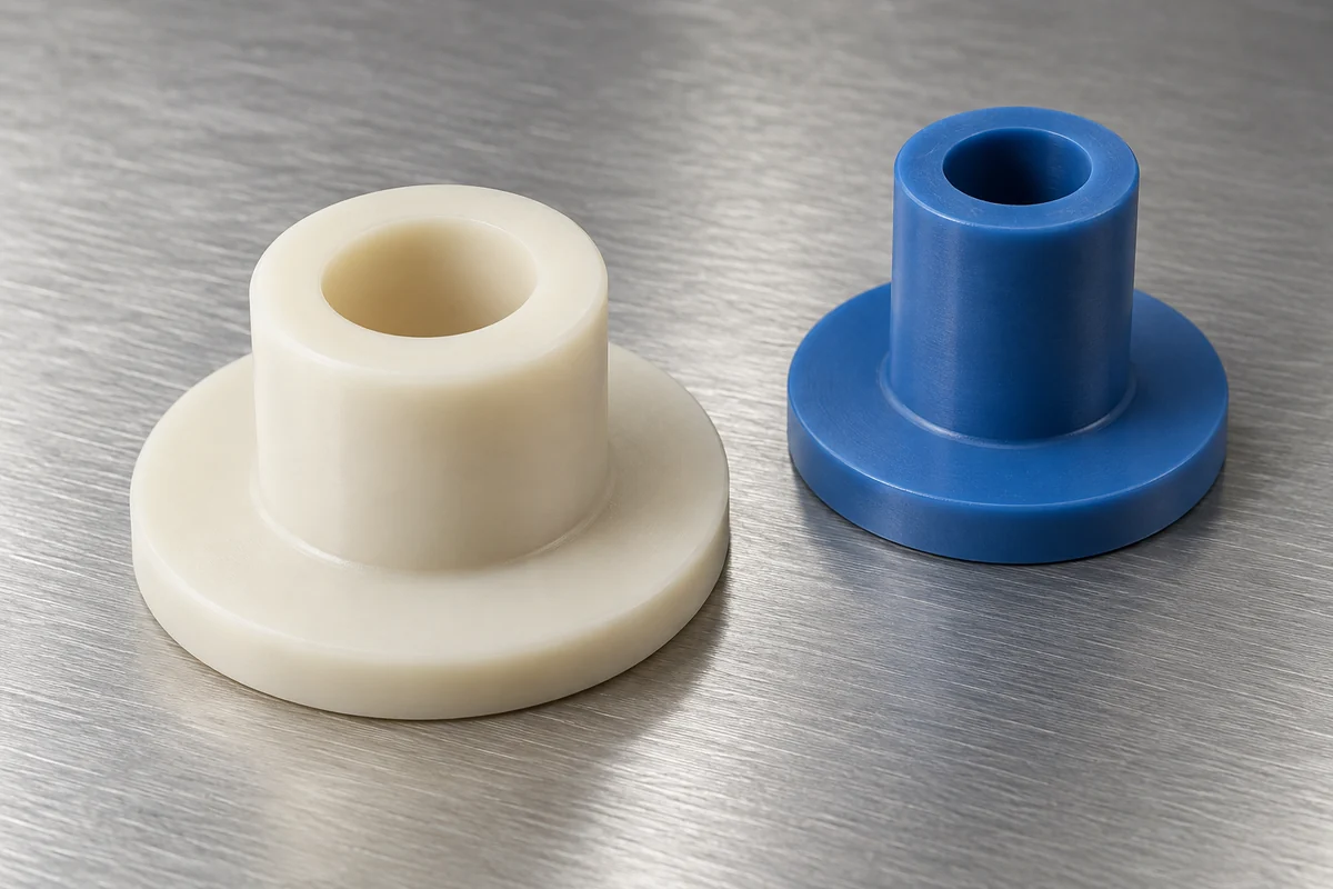
Stepped locating shoulder
Identify the locating diameter, its axial reference and the mating opening.
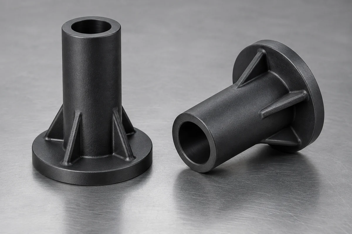
Ribbed standoff
Review rib roots, wall transitions and release direction together.
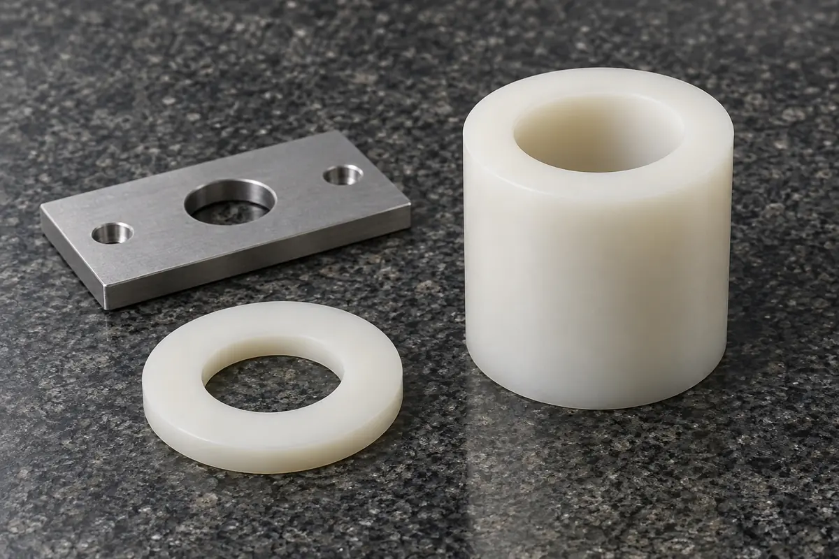
Bearing faces and stack
Review contact faces and the full stack; keep gate and ejection witnesses outside critical contact zones.
Illustrative configurations. Final specifications follow your approved drawings.
Application fit
Custom supports for static spacing and component location
Specify the gap the assembly needs, then define how the support creates and retains it.
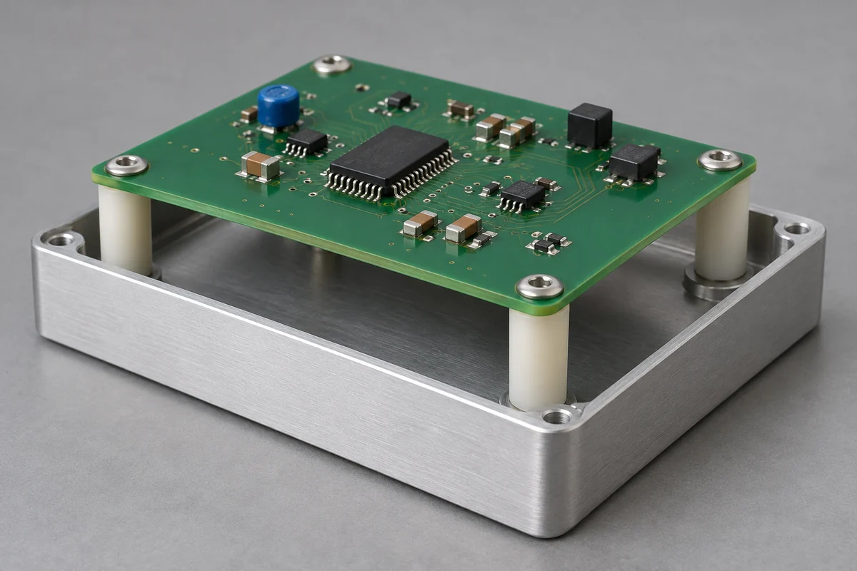
PCB-to-chassis supports
Review board height, fastening and locating references. Equipment insulation and safety ratings require separate validation.
Panel and enclosure spacing
Define contact faces, neighboring components and permitted installed movement.
Fixture and sensor supports
Evaluate repeatable location, clamping and service exposure affecting fit.
Quote-ready inputs
What to send for a meaningful quotation
Use the same drawing and requirements for every proposal. Mark open decisions explicitly so that a low price does not conceal a different deliverable.
| Area | Please provide | Review before release |
|---|---|---|
| Assembly | Drawing revision, mating components, gap and bearing faces. | Review the complete tolerance stack, not just the loose part. |
| Material | Exact grade, reinforcement, color and required condition. | Compare current grade data and control any substitution. |
| Fastening and load | Screw or insert, installation and service conditions. | Separate part inspection from preload, creep and equipment validation. |
| Tooling | Critical faces, draft restrictions, gate and witness limits. | Resolve release direction and wall transitions before tooling. |
| Supply | Sample quantity, repeat demand, inspection and packaging. | Define sample release, production controls and change responsibility. |
From drawing to approval
From support function to a controlled production drawing
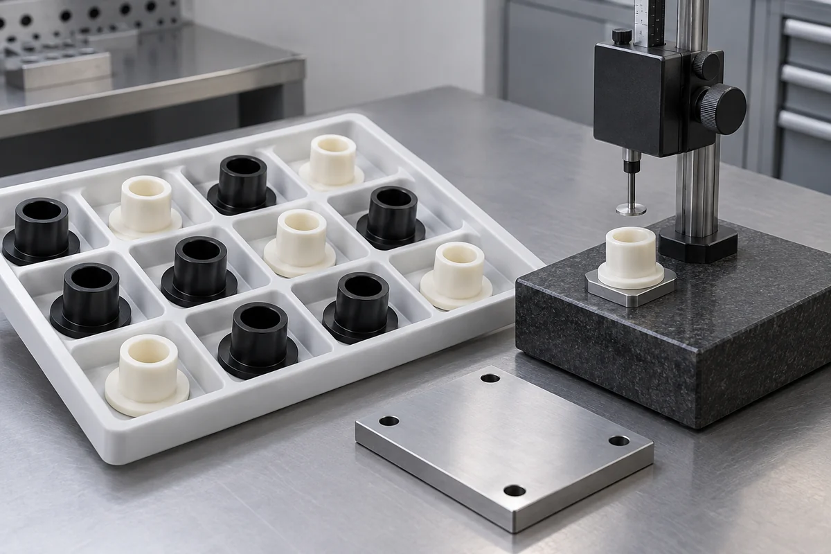
Review the full joint
Confirm mating revisions, material and the faces establishing installed distance.
Resolve DFM and tooling
Agree wall transitions, release, gate and measurement access before tool approval.
Measure and assemble samples
Check identified samples under agreed conditions, then evaluate the assembly.
Release repeat supply
Document the approved configuration and inspection plan; review changes against that baseline.
Practical engineering and buying guides
Decisions to make before production
- Nylon vs POM Plastic Spacers: Moisture, Load and Assembly FitCompare nylon and POM for custom plastic spacers using moisture condition, bearing load, assembly height and exact-grade evidence before tooling.
- Plastic Spacer Height Tolerances: Plan the Assembly StackDefine plastic spacer height from functional bearing faces, then review counterpart tolerances, conditioning, clamping and cavity-level inspection.
- Plastic Spacer Creep Under Bolt Preload: What to ValidateReview sustained compression, contact area, temperature and preload retention in plastic spacer joints without treating torque as a lifetime test.
- Injection-Molded vs Machined Plastic Spacers: Choosing a RouteCompare molding and machining for custom plastic spacers using design stability, material form, approval work and repeat demand—not quantity alone.
- Hollow vs Solid Plastic Spacers: Walls, Ribs and Bearing FacesReview hollow, thick-wall and ribbed spacer designs for molding. Balance bearing area, wall transitions, release direction and dimensional acceptance.
- Threaded Standoffs vs Unthreaded Plastic SpacersChoose threaded or through-bore plastic supports using the load path, service access, fastener engagement and a controlled assembly validation plan.
Before you request a quote
Do you sell standard spacers from stock?
This service covers custom molded parts. A standard component may suit an unchanged requirement; check that before commissioning custom tooling.
Is nylon always preferable to POM?
No. Exact grade, conditioning, fastening load and exposure determine the comparison. Material family alone does not establish assembly performance.
Can every feature hold the same tolerance?
Tolerances need feature-specific review of geometry, resin and inspection conditions. State functional requirements instead of one tight value for the entire drawing.
Can supports include threads or inserts?
These are options to review. Define the fastener, insert retention, secondary operations and assembly validation in the quotation scope.
What should accompany the CAD model?
Send the controlled drawing, mating parts, material requirements, sample quantity, repeat demand and required acceptance documentation.
Your next step
Discuss the part with its intended function.
Share the spacer, its mating components and the gap it must maintain. We can review a defined tooling, molding and sample-approval scope.
Explore our injection molding service or review other custom molded applications.