

| Film insert molding (FIM) places a pre-printed, thermoformed film into an injection mold cavity, then injects molten resin behind it. Heat and pressure fuse the film to the substrate in a single cycle, producing a part with permanently bonded graphics, textures, or functional surface layers. The process eliminates paint booths and solvent-based coatings entirely — reducing VOC emissions and secondary processing steps. |
The economics follow from that structure: the film carries all surface requirement. In this guide, you’ll learn how the four-stage film insert molding process works and how to choose a trusted manufacturing partner to accelerate your decorated plastic programs with precision and speed.
What Is Film Insert Molding?
Film insert molding — also called FIM or INS — belongs to the In-Mold Decoration (IMD) family. The distinguishing characteristic is that a functional, pre-formed film is permanently encapsulated into the part during the injection cycle, rather than applied as a post-mold coating or label.
The film is not a label. It is an engineered multi-layer structure: a printed graphic layer, a protective hardcoat (typically cured to pencil hardness 2H per ASTM D3363), and an adhesive tie-layer that bonds to the injected substrate. [1] This construction gives FIM parts a surface durability profile that post-mold decoration methods cannot replicate — because the hardcoat is applied before molding, not after, and the graphic layer is physically sandwiched inside or behind it.
FIM is also distinct from in-mold labeling (IML): IML places a flat label in the mold; FIM thermoforms the film to a three-dimensional shape before molding, enabling full wrap-around coverage on curved and contoured surfaces.
The Four-Stage Film Insert Molding Process
Each stage has specific tolerance and quality requirements. Failure at any one stage propagates to the final part — and because FIM integrates decoration and structure in a single shot, post-mold correction is not possible. The defect ships with the part.
Stage 1 — Graphic Design and Printing
FIM graphics are not designed for flat surfaces — they are engineered for the three-dimensional form they will eventually take. Specialized software pre-distorts the artwork to compensate for the predictable stretch pattern during thermoforming, so that text, icons, and color fields land correctly on the curved final part. Ink registration is held to ±0.1 mm across the printed film to prevent color drift on the finished part.
Silk-screen printing delivers saturated Pantone-matched colors with high-volume production capability and consistent opacity for backlit dead-front designs. Digital printing allows photographic image quality and faster prototype turnaround.
UV curing hardens the ink layer to 2H pencil hardness, and specialized edge-barrier coatings prevent metallic inks from oxidizing at trim lines — a failure mode that only manifests months into service if not addressed during the printing stage.
Stage 2 — Thermoforming
The flat printed film is heated above its glass transition temperature and formed under high-pressure air into the three-dimensional shape of the mold cavity. Advanced registration systems compensate for stretch-induced graphic shift during this forming step — the largest single source of positional error in a FIM program.
Thermoforming also achieves edge and corner wrap-around without visible resin witness lines. For backlit displays and touch interfaces, the quality of this wrap is critical: incomplete coverage creates light leakage at seams, and no post-mold process can correct it. The forming geometry must be engineered in concert with the mold design — not determined independently.
Stage 3 — Precision Trimming
The formed film is cut to net shape by CNC die or laser trimming to match the exact footprint of the mold cavity. Oversize film wrinkles or folds during injection; undersize film allows resin flash over the graphic area.
Trim tolerance is typically ±0.2 mm, and every trimmed film is inspected before proceeding to the molding stage — a defective film wastes the full part cycle time plus ejection and handling if discovered after injection.
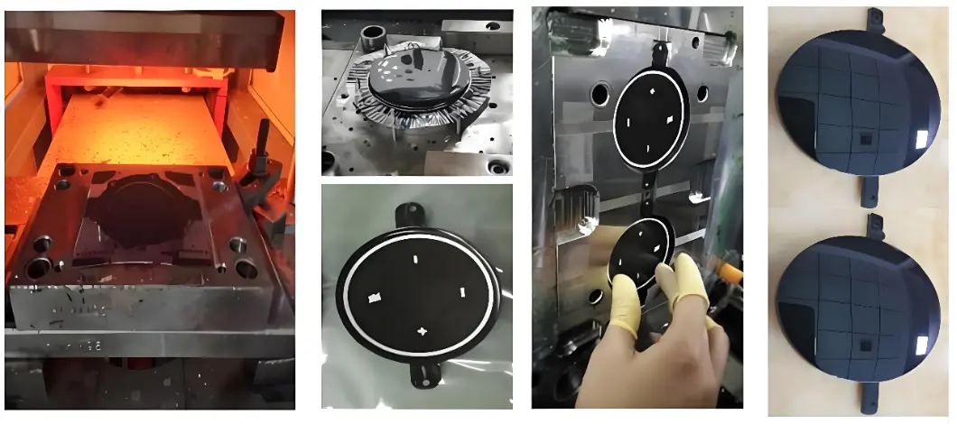
Stage 4 — Insertion and Injection Bonding
Robotic handling positions the trimmed film — printed side facing the cavity surface — in the mold with high repeatability. Molten resin injects behind the film, activating the adhesive tie-layer through heat and pressure. Controlled pack pressure and cooling rates manage differential shrinkage between the film and the substrate resin, which is the primary cause of post-mold warpage in FIM parts.
The film and substrate bond is permanent and chemical — not mechanical. The resulting part has a surface that will not peel, delaminate, or scratch through to a different color layer in the way that painted surfaces do. The encapsulation depth protects the graphic against abrasion, chemical cleaning agents, and UV exposure across the part’s service life.
Six Advantages of Film Insert Molding Over Post-Mold Decoration
Choosing film insert molding offers significant benefits ranging from visual appeal to environmental compliance. These advantages help you create better products while also streamlining your entire factory production line and reducing overhead costs.
Eliminates Paint Booths and Solvent-Based Coatings
Spray painting requires booths, masking fixtures, drying ovens, and solvent waste handling. FIM replaces all of this with the injection cycle itself. For electronics and consumer product programs subject to VOC regulations under frameworks such as IEC 62321, eliminating spray coating from the process removes the primary VOC emission source in the manufacturing cell. [3]
Permanent Graphics That Cannot Peel or Fade
FIM graphics are encapsulated inside the part structure or sealed beneath a hardcoat — not applied on top of a surface that can abrade, chip, or delaminate. The hardcoat layer (2H pencil hardness minimum per ASTM D3363) protects the graphic from mechanical abrasion, chemical cleaning agents, and UV exposure. This durability profile exceeds painted surfaces in high-touch or frequent-clean applications.
Full Edge Wrap on 3D Geometry
The thermoforming stage shapes the film to the part’s contour before injection, enabling wrap-around coverage on curved surfaces, corners, and sidewalls — without visible seams or resin witness lines. This is not achievable with post-mold labels or painting, both of which leave visible edge boundaries on non-planar surfaces.
Design Changes Without Mold Modification
Artwork changes — color updates, icon revisions, regional variant text — require only a new print run. The mold is unchanged. For product lines that require frequent design refreshes, this eliminates the tooling cost and lead time that painting line changes or new mold orders would require.
Capital and Floor Space Reduction
One tool, one machine, and one cycle replace entire painting lines with associated ovens, booths, and masking stations. The floor space, capital equipment, and operating labor for post-mold decoration are eliminated in a single process consolidation.
This reduction is most significant for programs that previously required multiple decoration steps — prime coat, base coat, topcoat — each with its own equipment and handling.
Enables Functional Surfaces — Backlighting and Haptics
Dead-front backlighting — a surface that appears opaque under ambient light but transmits illumination when backlit — is a FIM-specific capability. The ink stack on the film controls exactly which areas transmit light and which block it, with positional accuracy that painting cannot achieve.
Tactile textures — brushed metal, carbon fiber, soft-touch grain — are printed directly onto the film, eliminating the embossing or coating steps required to add texture post-mold.
Material Compatibility: Film and Resin Pairing
The film and injected substrate must be chemically compatible at the tie-layer — they must bond under the heat and pressure of the injection cycle without delaminating in service. Material pairing is the most common source of FIM qualification failures and must be verified before tooling is committed.
Common Film Materials
- Polycarbonate (PC) film: highest optical clarity and impact resistance; standard for display windows and backlit interfaces; PMMA over-coat option for maximum scratch resistance.
- Polyethylene terephthalate (PET) film: excellent print surface quality; cost-effective; standard for consumer product fascias and appliance controls.
- Polyurethane (PU) film: soft-touch and flexible applications; accommodates tighter 3D forming radii than rigid films; used for ergonomic grip panels and flexible wearable interfaces.
- PMMA (acrylic) film: premium optical clarity; hardest standard surface coating; used for high-end consumer electronics display covers.
Substrate Compatibility
The injected substrate resin must be chemically compatible with the film’s adhesive tie-layer. PC film bonds reliably to PC and PC/ABS substrate resins. PET film pairs with ABS and ABS/PC substrates. Mismatched pairs — for example, PET film on a PA66 substrate without an appropriate tie-layer — produce delamination under thermal cycling or chemical exposure, often not apparent until field service.
Processing temperatures must also align: the substrate resin’s melt temperature cannot significantly exceed the film’s heat deflection point at the film-cavity interface, or the film will distort or burn during injection. This thermal compatibility constraint is the second most common source of FIM qualification failures after material chemical incompatibility.
Design Considerations for Film Insert Molding Programs
FIM only works when the mold respects the film as much as the resin. Here are the four design decisions that make or break the program.
Film Registration and Locating Features
The mold must include positive registration features — pins, ledges, or vacuum ports — that hold the trimmed film in the exact cavity position required. Without registration features, film position varies shot-to-shot, producing graphic misalignment that fails cosmetic inspection. Registration tolerance in the mold must be tighter than the graphic placement tolerance specified on the part drawing.
Venting at the Film Interface
Air trapped between the film and the cavity surface during injection produces bubbles, blisters, and surface distortion on the finished part. Vents must be located at the last-fill areas of the film interface — typically at the film’s outer perimeter — at depths of 0.01–0.02 mm.
Vacuum-assist venting is often specified for complex 3D surfaces where directional venting is insufficient to clear all trapped air.
Thermal Management at the Film Zone
The film zone requires controlled, uniform cooling to prevent differential shrinkage between the film and the substrate. If the film side of the mold runs significantly hotter or cooler than the substrate side, the mismatch in shrinkage rates causes warpage after ejection.
Dedicated cooling channels adjacent to the film cavity face — within 1.5× channel diameter of the surface — maintain the temperature uniformity required for flat, warp-free FIM parts.
Gate Location Away from Film Graphics
The gate location must be positioned away from critical graphic areas. The high-shear flow front at the gate creates a thermal and mechanical disturbance at the film surface that can shift registration, cause whitening, or damage the ink layer.
Fangate or film-gate designs that distribute the flow front before it contacts the graphic area are preferred for programs with tight registration requirements.
Conclusion
Film insert molding achieves what post-mold decoration cannot: graphics, textures, and functional surface layers that are permanently integrated into the part structure — not applied on top of it. The four-stage process from printed film to bonded part replaces spray booths, ovens, and secondary labor with a single injection cycle, consolidating capital and eliminating the VOC emissions that coating processes generate.
Success in FIM depends on three capabilities working together: graphic engineering that compensates for 3D film distortion, mold design that integrates film registration and thermal management into the tool, and material pairing that maintains film-substrate bond integrity across the part’s service life.
At Fecision, we combine deep molding knowledge with a strong promise of high precision and green manufacturing. Send your part drawing and graphic requirements to our engineering team today for a free technical talk and a fair quote on your next project.
Frequently Asked Questions
What is the difference between film insert molding and in-mold labeling?
In-mold labeling (IML) places a flat label in the mold and bonds it during injection. Film insert molding (FIM) thermoforms the film to a three-dimensional shape before molding, enabling full wrap-around coverage on curved surfaces and corners without visible seams. FIM also uses multi-layer engineered films with hardcoats and adhesive tie-layers, whereas IML typically uses simpler flat film stock.
What film materials are compatible with polycarbonate substrates?
PC film bonds reliably to PC and PC/ABS substrates via compatible adhesive tie-layers — the most common FIM material pair for electronics displays and medical device panels.
- PMMA film over a PC substrate provides maximum surface hardness.
- PU film bonds to PC substrate for flexible or soft-touch surfaces.
- PET film is not typically paired with PC substrates due to tie-layer compatibility issues.
How does FIM achieve backlighting effects in plastic parts?
Dead-front backlighting in FIM parts is achieved by printing the film with an opaque base layer that blocks visible light under ambient conditions, plus transparent or translucent windows at icon and symbol locations. When backlit, only the window areas transmit illumination.
What causes delamination in film insert molded parts?
Delamination at the film-substrate interface is caused by chemical incompatibility between the film’s tie-layer and the injected resin, excessive differential shrinkage from thermal mismatch during cooling, or inadequate pack pressure during injection.
How are FIM graphics inspected for production quality?
FIM graphic inspection covers registration accuracy (film position versus nominal per part drawing), ink density and color consistency, hardcoat integrity (pencil hardness per ASTM D3363), and absence of air bubbles, blisters, or folds at the film-cavity interface.
First-article inspection is performed on 100% of dimensions. In production, automated vision systems check registration and surface quality at production rate; hardcoat testing is performed on statistical samples.
References
Accessed May 2026.
[1] ASTM International. ASTM D3363 — Standard Test Method for Film Hardness by Pencil Test. https://www.astm.org/d3363-05r11e02.html
[2] Society of Plastics Engineers (SPE). ‘In-Mold Decoration Technical Reference.’ SPE Technical Library. https://www.4spe.org/
[3] International Electrotechnical Commission. IEC 62321 — Determination of Levels of Restricted Substances in Electrotechnical Products. https://www.iec.ch/standards/63185


