

| Medical insert molding is a single-shot process where a pre-formed insert — typically metal, ceramic, or rigid polymer — is positioned in a mold cavity before injection. Molten biocompatible thermoplastic then flows around the insert and bonds through mechanical interlock and chemical adhesion, producing one indivisible component. The result: metal-grade structural performance with polymer flexibility, biocompatibility, and cleanroom-ready production. |
Catheters, surgical grips, pacemaker housings, and diagnostic connectors all rely on this process. What makes it the default choice in medical device manufacturing is not just the strength of the bond — it is the elimination of secondary assembly steps that each introduce contamination risk, misalignment error, and regulatory documentation complexity.
Below you’ll learn what insert molding truly is, why it dominates med-tech manufacturing, and where it appears in real devices. You will find practical insights to improve your next project.
What Is Medical Insert Molding?
Medical insert molding positions a pre-formed substrate — stainless steel 17-4PH, titanium Ti-6Al-4V, ceramic alumina, or pre-molded polymer — inside a mold cavity. The mold closes, molten resin fills the cavity under controlled pressure and temperature, and the plastic locks onto the insert’s surface geometry as it cools.
The bond relies on two mechanisms working together. Mechanical interlock comes from plastic flowing into undercuts, knurls, and through-holes (typical undercut depth: 0.1–0.3mm). Chemical adhesion depends on surface energy compatibility — the insert surface should exceed 38 dynes/cm for reliable polymer wetting. Together, these mechanisms achieve shear bond strengths of 15–40 MPa in production tooling.
This is fundamentally different from gluing or press-fitting a metal component. No adhesive degrades, no mechanical joint loosens under cyclic load, and no secondary operation introduces a potential contamination point.
How the Process Cycle Works
Each cycle follows four controlled stages. The sequence is straightforward; the precision requirements are not.
- Preparation and pre-heating: Inserts are cleaned, inspected, and — when their mass exceeds roughly 50g — pre-heated to 150–200°C. Pre-heating reduces thermal shock when hot plastic contacts cold metal, preventing micro-cracking in the surrounding polymer during solidification.
- Placement: Inserts are loaded onto locating pins inside the mold cavity. Automated robotic loading achieves positioning repeatability of ±0.05mm, which is necessary for micro-scale components where manual placement introduces variation. At lower volumes, manual loading with vision verification is standard.
- Injection: Molten resin fills the cavity at controlled pressure (typically 500–1,500 bar for engineering thermoplastics) and temperature. Gate placement is critical — gating directly at the insert face can cause hydraulic pressure to displace it before plastic solidifies around it. Gates should feed the cavity from the side or behind the insert.
- Cooling and solidification: As plastic cools, it contracts around the insert — amplifying the mechanical grip on knurled and undercut surfaces. Metal inserts conduct heat faster than the surrounding polymer, which can create local differential shrinkage. Balanced cooling channels compensate for this.
Insert Molding vs. Overmolding vs. Multi-Shot Molding
• Insert Molding: Single-shot encapsulation of pre-formed rigid substrates (stainless steel 17-4PH, titanium Ti-6Al-4V, ceramic alumina) with thermoplastic. Bond mechanism: mechanical interlock (undercut depth 0.1-0.3mm) + chemical adhesion (surface energy >38 dynes/cm).
• Overmolding: Multi-shot process molding thermoplastic elastomer (TPE) over rigid thermoplastic substrate. No metallic insert; bond relies on thermal fusion between polymer layers.
• Multi-Shot Molding: Two+ polymers injected sequentially via rotating mold or transfer station. Distinct from insert molding which uses solid metallic inserts.
These three processes produce multi-material parts, but they solve different problems. The table below maps the key engineering differences.
| Parameter | Insert Molding | Overmolding | Multi-Shot Molding |
| Substrate | Metal, ceramic, or rigid polymer | Rigid thermoplastic (no metal insert) | Two or more thermoplastics |
| Bond mechanism | Mechanical interlock + chemical adhesion | Thermal fusion between polymer layers | Cohesive bond between injected polymers |
| Bond strength | 15–40 MPa (shear) | 5–12 MPa (peel) | 8–15 MPa (cohesive) |
| Cycle time | 15–45 s | 20–60 s (2 shots) | 25–70 s |
| Tooling cost | Moderate — high precision required | High — two barrels required | Very high — rotary platen or transfer |
| Hermeticity | Excellent — true mechanical seal | Moderate — seam line at interface | Moderate |
| Best for | Structural integration of metal + plastic | Ergonomic grips, soft-touch surfaces | Multi-material aesthetic components |
Rule of thumb: if the goal is integrating a metal or ceramic component into a plastic structure, insert molding is the correct process. If the goal is adding a soft ergonomic or sealing layer over an existing plastic substrate, overmolding is appropriate. Both can — and often do — appear on the same device.
→ See also: Overmolding vs. Insert Molding — Detailed Comparison
Six Key Benefits of Medical Insert Molding
The advantages of insert molding in medical manufacturing are practical, not abstract. Each addresses a specific challenge in device design, regulatory compliance, or production economics.
1. Metal-Grade Strength Where It Is Needed
Metal inserts handle tensile loads, torque transmission, and fatigue cycling — tasks that engineering thermoplastics cannot reliably sustain alone. The polymer jacket provides electrical insulation, chemical resistance, and ergonomic geometry around that metal core.
The bond between the two is not a fastener or an adhesive — it is a permanent mechanical interlock formed under injection pressure. A brass insert in PA66, for example, delivers pull-out resistance of 3.5–4.5 kN — approximately three to five times higher than a tapped plastic thread in the same material.
2. Sub-Millimetre Precision at Scale
Insert molding produces dimensional consistency that secondary assembly cannot match. When inserts are robot-loaded and cavity locations are machined to ±0.01mm, every part in a production run shares the same insert position relative to the mold geometry.
For micro-scale devices — marker bands in catheter shafts, sensor contacts in wearable patches — this positional consistency is not a quality improvement. It is a functional requirement. A marker band shifted 0.2mm from its intended position produces a different X-ray signal and a different clinical interpretation.
3. Design Freedom with Dissimilar Materials
Insert molding accepts combinations that cannot be chemically bonded: stainless steel to PEEK, titanium to PC, ceramic sensor elements to TPU housings. The bond relies on geometry, not material compatibility — so material selection can focus entirely on functional performance rather than adhesion chemistry.
This allows each material in the assembly to be optimised for its specific role: the metal handles load, the polymer handles biocompatibility and geometry, and the insert geometry handles their interface.
4. Assembly Elimination
Each component eliminated from a final assembly reduces: one fixture, one handling step, one potential misalignment, one contamination event, and one documentation requirement under ISO 13485.
An insert-molded catheter hub that integrates the metal collar, the polymer body, and the strain relief in one shot replaces three separately manufactured components, two bonding operations, and two assembly inspection points. At scale, this drives both cost reduction and quality improvement simultaneously.
5. Hermetic Sealing for Implantable and Fluid-Handling Devices
Molten polymer under injection pressure fills every surface feature on the insert, including micro-grooves and threads invisible to the eye. As the plastic cools and contracts onto the metal, it forms a mechanical seal around the insert perimeter. This seal is repeatable, validated, and does not degrade in service.
For pacemaker housings, neurostimulator enclosures, and IV fluid connectors, this hermetic performance is the defining functional requirement. A post-mold adhesive seal or gasket introduces an additional failure mode and an additional validation step. Insert molding eliminates both.
6. Cost Efficiency at Volume
High-cavitation insert molding tooling amortises its cost across high annual volumes. Once a 16-cavity tool is qualified and running at 30-second cycle times, the per-unit cost is dominated by material cost — not labour or machine time.
The break-even comparison with manual assembly varies by part complexity, but for most disposable medical device components, insert molding becomes economically favourable above approximately 20,000–50,000 parts per year. Below this volume, bridge tooling or manual insertion may offer better economics during early clinical phases.
Materials for Medical Insert Molding
Material selection in medical insert molding involves two paired decisions: the insert material and the plastic resin. Both must perform under the device’s service conditions — and both must survive the sterilisation method chosen for the device’s lifecycle.
Plastic Resins
The choice of resin determines biocompatibility, sterilisation compatibility, mechanical properties, and how well the plastic bonds to the insert geometry. The table below covers the most common resins in medical insert molding programs.
| Material | Stiffness | Key Properties for Insert Molding | Typical Medical Applications |
| PEEK | Very high | Biocompatible, bone-like modulus (3.6 GPa), autoclave-stable to 134°C, chemical inertness | Spinal implants, trauma fixation components, dental abutments, reusable surgical instruments |
| PA66-GF30 | High | Glass-filled nylon — high stiffness, insert grip via shrinkage, moisture-sensitive pre-dry required | Diagnostic housings, surgical instrument bodies, enclosures for electronic assemblies |
| Polycarbonate (PC) | High | Optical clarity, impact resistance, autoclave-limited — sterilise by EtO or gamma for PC | Catheter hubs, transparent diagnostic components, sensor housings |
| PBT | Moderate–High | Low moisture absorption, good dimensional stability post-sterilisation, excellent for connectors | Electrical connectors, relay housings, fluid management fittings |
| TPU | Moderate | Flexible, biocompatible, kink-resistant — ideal partner for metal hypotubes | Balloon catheters, infusion ports, vascular sheath bodies, wearable device seals |
| LSR | Low (flexible) | Platinum-cured silicone — inherently biocompatible, sterilisation-compatible by all methods, USP Class VI | Respiratory masks, long-term implant seals, drug-contact diaphragms |
Material pre-drying is not optional. PA66, PBT, and PC are hygroscopic — they absorb atmospheric moisture that converts to steam at barrel temperatures, creating voids, splay marks, and degraded mechanical properties. All hygroscopic resins must be dried in desiccant ovens to the manufacturer’s specified moisture content before processing, typically 0.02–0.2% depending on material.
Insert Materials
Metal inserts in medical applications fall into three common categories:
- Stainless steel 17-4PH: High hardness, excellent fatigue resistance, MRI compatibility varies by grade. Standard for surgical instrument shafts, catheter collars, and fluid connectors.
- Titanium Ti-6Al-4V: Superior strength-to-weight ratio, fully biocompatible, MRI-safe, higher cost than stainless. Used for long-term implantable device housings and load-bearing orthopaedic components.
- Brass C36000: Easiest to machine, closest thermal expansion coefficient to engineering plastics — reducing interface stress. Standard for threaded inserts in diagnostic and monitoring device housings where corrosion is not a concern.
- Ceramic alumina: Chemically inert, electrically insulating, wear-resistant at high temperatures. Used for sensor elements, implantable electrode substrates, and components requiring dielectric performance.
Sterilisation Compatibility by Method
The sterilisation method is a material selection constraint, not an afterthought. Confirm sterilisation compatibility before finalising resin selection.
| Method | Compatible | Caution | Notes |
| Autoclave (Steam 121–134°C) | ✅ PEEK, PPSU ✅ Polypropylene | ⚠️ PC (limited cycles) ⚠️ PBT (check grade) | Degrades PC above ~15 cycles. PEEK and PPSU are the preferred choices for repeatedly autoclaved reusable instruments. Acetal (POM) should not be autoclaved. |
| Ethylene Oxide (EtO) | ✅ PC, PBT, TPU ✅ Most thermoplastics | ⚠️ LSR (long aeration) | EtO is the most compatible method for heat-sensitive plastics. Aeration time of 12–24 hours is required to remove residual EtO — critical for patient contact devices. Validated per ISO 11135. |
| Gamma Irradiation | ✅ PEEK, PP, PE ✅ PC (low dose) | ⚠️ PVC discolours ⚠️ PTFE degrades | Dose typically 25–50 kGy. Some polymers yellow or embrittle at high dose. Radiation-stabilised grades are available for sensitive resins. Validated per ISO 11137. |
| E-Beam | ✅ PEEK, PP ✅ TPU, PE | ⚠️ Dose-sensitive resins | Similar to gamma but faster penetration and lower secondary activation. Preferred for thin-walled single-use devices. Less penetrating than gamma for dense assemblies. |
→ See also: ISO 10993 Biocompatibility Standards for Medical-Grade Silicone
Applications of Medical Insert Molding
Insert molding appears throughout the medical device ecosystem — in single-use disposables, reusable instruments, and long-term implantables. The common thread is a requirement for precision, biocompatibility, and integration of metal and polymer in a single production step.
Catheters and Guidewires
Metal collars encapsulated into catheter shafts provide torque transmission points — the mechanism that allows a surgeon to rotate the distal tip by turning the proximal hub. Without a rigid metal interface at this transition, torque is lost to shaft compliance and the catheter becomes unresponsive.
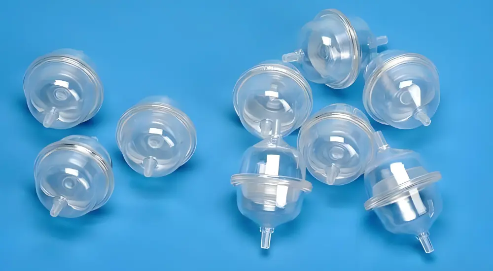
Radiopaque marker bands (typically platinum or gold, 0.5–2mm wide) are insert-molded into shafts to create reference points visible under X-ray or fluoroscopy. The one-piece design eliminates the small crevice that would exist if a band were adhesively bonded — a crevice that traps bacteria and creates cleaning validation problems.
Surgical Instruments
Blades, electrodes, and cannulae locked into polymer handles give surgeons a combination of properties that no single material provides: the cutting performance or electrical conductivity of metal, the ergonomic grip and electrical insulation of polymer.
In electrosurgical instruments — cauterising pens, bipolar forceps, monopolar scissors — the insulation barrier between the electrode and the handle is safety-critical. Insert molding creates this barrier in a single process step, verified by dielectric testing on every production lot.
Implantable Devices
Pacemakers, neurostimulators, and implantable drug pumps house electronics, batteries, and fluid reservoirs within hermetic polymer shells. These shells must prevent body fluid ingress for years to decades of continuous service.
Biocompatible grades meeting ISO 10993 and long-term implant requirements (Class III per ISO 10993-1:2025) are mandatory. The molding process creates a seamless enclosure around the metal chassis and electronic subassemblies — with no joints, seams, or adhesive interfaces that could fail over time.
Diagnostic and Monitoring Equipment
Sensor housings and wearable patch connectors integrate conductive signal paths, strain reliefs, and sealing features in a single molded component. The alternative — building these functions from separately fabricated and assembled parts — multiplies the number of potential failure points and the complexity of the quality record.
Insert molding is particularly valuable for wearable devices that must survive repeated daily handling, patient perspiration, and cleaning with medical disinfectants. The encapsulated design is inherently resistant to liquid ingress and mechanical separation under these conditions.
Fluid Management Components
IV connectors, stopcock valves, and infusion sets encapsulate metal or ceramic valve seats to create leak-proof fluid interfaces that maintain their sealing performance across the device’s rated pressure range.
The injected polymer flows into every micro-groove of the valve seat geometry under pressure, then contracts onto those features during cooling. This creates a seal that has been subjected to full injection pressure during formation — not a seal applied after the fact by a gasket or adhesive.
Drug Delivery and Soft-Tissue Intervention
TPU insert molding produces balloon catheter bodies and infusion port housings that combine the kink resistance and flexibility of elastomer with the pushability and torque response of an encapsulated metal hypotube.
This material combination — rigid metal core, compliant polymer jacket — is what allows a catheter to navigate a tortuous vascular pathway while still responding to the operator’s hand movements at the proximal end. Neither material alone achieves this.
Dental and Orthodontic Components
Implant drivers and bracket bases merge titanium or stainless inserts with FDA-cleared polymers for high-torque transfer without the risk of tool fracture or patient injury. Titanium’s biostability and PEEK’s bone-like modulus make this pairing particularly effective for components that contact both instrument and tissue during a procedure.
Process Validation: IQ/OQ/PQ for Medical Insert Molding
Medical insert molding is classified as a ‘special process’ under ISO 13485 — the process output cannot be fully verified by downstream inspection alone. A part can be dimensionally conforming yet have inadequate insert bond strength, incomplete encapsulation, or residual stress that will cause failure in service.
This makes process validation mandatory under ISO 13485 Clause 7.5.6, and it is why medical device OEMs require IQ/OQ/PQ documentation from their molding suppliers — not just dimensional inspection reports.
Installation Qualification (IQ)
IQ verifies that all equipment and tooling are installed correctly and operate to specification before any production trials begin.
- Press calibration records — injection pressure, barrel temperature zones, clamping force
- Insert handling system verification — robotic placement accuracy, gripper condition, vision system calibration
- Mold thermocouple calibration — confirmed to ±1°C across all zones
- Material certifications — CoA confirming resin lot meets ISO 10993 biocompatibility and UL or FDA-registered grade specifications
Operational Qualification (OQ)
OQ establishes the processing window — the parameter range within which conforming parts are consistently produced. For insert molding, this means testing parameter combinations systematically.
- Barrel temperature variation (±5°C from nominal) — confirm dimensional and bond strength conformance at limits
- Injection pressure variation (±50 bar) — confirm complete fill and no flash at limits
- Insert pre-heat temperature range — confirm minimum temperature above which adequate bond strength is achieved
- Gate freeze time variation — confirm minimum packing time that prevents sink marks or voids adjacent to the insert
OQ defines the Design Space — the validated range of parameters that the process can operate within during routine production. Any production run outside this range triggers a deviation record and, depending on severity, a re-qualification event.
Performance Qualification (PQ)
PQ demonstrates that the process, operating within the OQ-established parameter range, consistently produces conforming parts across three consecutive production runs at commercial batch size.
- Cpk ≥ 1.33 on all critical dimensions (Cpk ≥ 1.67 on critical-to-quality features — the standard for regulated medical programs)
- Pull-out force testing per batch — minimum force specified in the Device Master Record
- First article CMM report — all features within drawing tolerance
- Visual inspection AQL — zero critical defects, defined AQL for minor defects
PQ documentation becomes part of the Design History File (DHF) and is available for FDA review during a 510(k) submission or routine manufacturing site inspection.
Design for Manufacturability (DFM) in Medical Insert Molding
DFM for insert molding means designing both the part geometry and the insert geometry to produce a reliable, repeatable bond — not just a functional part. Most insert molding failures that appear in production actually originate in design decisions made before any steel was cut.
Wall Thickness Around the Insert
The minimum plastic wall surrounding an insert is 0.8mm — but this should be treated as a floor, not a target. Walls below 1.2mm are prone to cracking from the hoop stress created as plastic contracts onto the insert during cooling.
The recommended formula for boss geometry: boss outer diameter ≥ 1.5× the insert outer diameter. This ensures sufficient wall cross-section to contain the thermal contraction force without cracking, even after repeated sterilisation cycles that create additional thermal cycling stress.
Insert Surface Features
A smooth cylindrical insert relies entirely on compressive shrinkage for retention — which is inadequate for most service loads. Knurled patterns, annular grooves, and undercuts create mechanical interlocking geometry that dramatically increases both pull-out resistance and torque resistance.
Diamond-knurl patterns (0.5–1.0mm pitch) achieve the highest pull-out force per unit area. Helical undercuts improve axial retention while allowing controlled rotation. For ceramic inserts — which cannot be knurled — through-holes or flats on the insert perimeter provide the interlocking surface.
Gate Placement
Gate location relative to the insert is the DFM decision that most frequently causes first-article failure. Gating directly at an insert face creates a high-velocity plastic jet that displaces the insert off its locating pin before sufficient plastic has solidified to hold it in place.
Gates should feed the cavity wall, not the insert directly. For multi-cavity tooling, balanced runner layouts ensure that all cavities fill simultaneously — preventing pressure differentials that can shift inserts in low-pressure cavities.
Venting
Insert features — particularly undercuts and back faces — create dead-end zones that trap air during injection. Trapped air produces burn marks, incomplete fill in knurl channels, and weak weld lines behind the insert. Vents at 0.01–0.02mm depth placed at all end-of-fill zones and around insert positions allow gas to escape without allowing flash.
Pre-Heating Large Metal Inserts
Metal inserts above approximately 50g conduct heat away from the adjacent polymer rapidly during injection. The plastic immediately surrounding the insert begins to solidify before filling is complete, creating voids and weak bond zones.
Pre-heating inserts to 150–200°C before loading slows the thermal gradient and gives the plastic time to fill every surface feature before it begins to solidify. This step is particularly important for titanium and stainless steel inserts in PEEK programs, where barrel temperatures exceed 380°C and the temperature differential with a cold insert is severe.
Frequently Asked Questions
What is the difference between insert molding and overmolding in medical manufacturing?
Insert molding integrates a dissimilar substrate — almost always metal or ceramic — into a plastic part in a single shot. The bond is primarily mechanica. No chemical compatibility between the two materials is required.
Overmolding applies a second plastic material over a first plastic substrate. The bond is primarily chemical, so the two polymers must be compatible. It does not integrate metal components.
Why is medical insert molding better than press-fitting or adhesive bonding?
Insert molding forms the metal-to-plastic bond during injection — molten plastic at full injection pressure flows into every knurl groove, undercut, and through-hole on the insert surface, then contracts around those features during cooling. The result is a mechanical interlock that was formed under the same pressure that filled the cavity.
Press-fitting relies on interference tolerances that can relax under thermal cycling and repeated sterilisation. Adhesive bonding introduces a chemical interface that degrades under EtO, gamma irradiation, and autoclaving — and adds an assembly step with its own validation requirements.
How do you prevent insert shift during medical injection molding?
Three specific controls prevent it:
- Gate placement: Never gate directly at the insert face. Position gates to feed the cavity wall, not the insert, so the initial pressure front approaches the insert from the side rather than pushing it axially.
- Locating pin fit: The locating pin must provide firm positive location — the insert should not rattle on the pin. Too tight risks splitting the insert; too loose allows axial displacement under pack pressure.
- Injection profile: Use a slow initial fill stage (5–10% of full injection speed) until the cavity partially solidifies around the insert perimeter, then ramp to full injection speed to complete fill.
Conclusion
Medical insert molding is the process that allows a single manufactured component to do the work of an assembled subassembly — combining metal structural performance with polymer biocompatibility, geometry flexibility, and cleanroom-compatible production in one validated step.
The result is not just a lighter or cheaper part. It is a part with fewer potential failure modes, a simpler quality record, and a faster regulatory path — because there are fewer joints to validate, fewer materials to biocompatibility-test, and fewer assembly steps to qualify.
Getting the most from this process requires alignment between design, material selection, and supplier capability from the earliest phase of development. A DFM review before tooling begins is the most cost-effective investment available in a medical device program.
Fecision has over decades of experience in medical injection molding. We deliver ISO 13485-certified medical insert molding from prototype through commercial scale. Contact us to request a DFM review and material compatibility analysis today!
References & Sources
Accessed April 2026.
[1] ISO 13485:2016, Medical devices — Quality management systems — Requirements for regulatory purposes. Clause 7.5.6: Validation of processes for production and service provision. International Organization for Standardization. https://www.iso.org/standard/59752.html
[2] Kaysun Corporation. ‘Medical Injection Molding — IQ/OQ/PQ Validation.’ (IQ/OQ/PQ stage definitions; CPK ≥1.67 standard for medical programs; DFM and mold flow analysis practices.) https://www.kaysun.com/medical-injection-molding


