
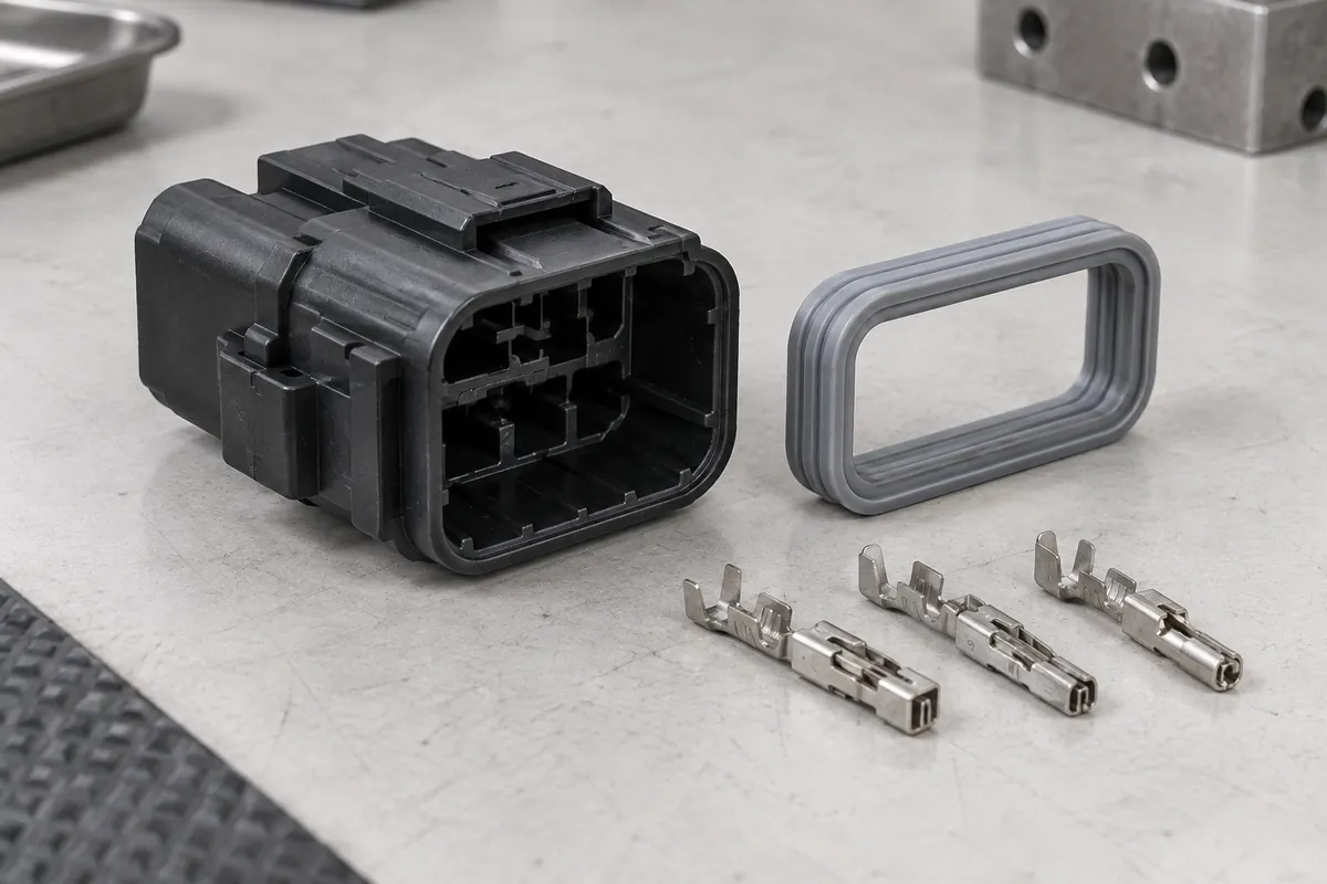
A molded insulator can match its drawing and still be part of an assembly that leaks, fails to latch or does not meet an electrical requirement. That does not make the plastic inspection meaningless. It means the complete connector has additional interfaces and acceptance conditions that must have an owner.
Define acceptance at three levels: the molded component, its interfaces and the completed assembly. This keeps a plastic-part quotation from accidentally promising contact performance, sealing qualification or product certification. It also prevents real interface needs from being dismissed simply because another supplier makes the mating piece.
Product design illustrations. Final geometry, materials and acceptance criteria are project-specific.
Name the delivered component precisely
Use “molded connector insulating body” or “terminal carrier” when that is what will be supplied. State whether metal contacts, elastomer seals, locking pieces or assembly operations are included. An exploded assembly view is useful because it makes the boundary visible without relying on the broad word “connector.”
For each item outside the molding scope, identify its drawing owner and the information needed from that owner. The molder may need the contact envelope or seal interface to review the plastic geometry even when those parts are not being purchased from the molder. Sharing an interface does not transfer responsibility for the complete assembly automatically.
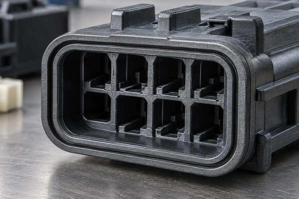
Separate contact location from electrical performance
The plastic carrier may locate, guide or retain terminals. Define those mechanical functions using the approved geometry and agreed assembly checks. The contact material, plating, contact force and electrical test requirements belong to their own controlled specifications. Do not use an empty-carrier dimensional report as evidence of finished contact resistance or current capability.
Where terminal installation loads or retention checks are required, name the actual terminal revision and installation method. A smooth surrogate pin may be suitable for a specific dimensional gauge but may not reproduce the intended assembly action. State what the surrogate represents and what remains to be checked with real components.
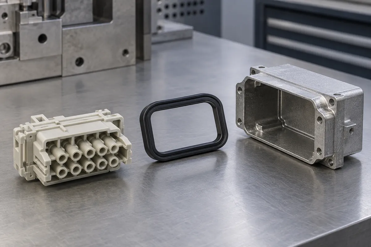
Treat a sealing land as one part of a sealing system
A groove or flat land on the molded part can be measured, but sealing also depends on the mating surface, seal material, assembly condition and specified environment. Mark the plastic's critical surfaces and permitted defects on the drawing. Assign responsibility for the seal selection and for assembled-system testing separately.
A leak check or ingress-protection claim needs an agreed method and the relevant assembled configuration. No universal IP rating follows from molding a groove, selecting a water-resistant resin or using a supplier's gasket. If the customer requires a particular rating, obtain the applicable qualification scope from the responsible engineering or test organization before the quote is finalized.
| Level | Typical evidence to define | Owner to name |
|---|---|---|
| Molded plastic | Material identity, dimensional report, appearance and cavity records. | Molder and customer component-approval authority. |
| Contact interface | Terminal fit, installation and retention checks using identified components. | Terminal/assembly design owner and agreed test provider. |
| Seal interface | Plastic land or groove inspection plus assembled sealing method. | Seal/system design owner and agreed test provider. |
| Complete connector | Applicable electrical, environmental and end-product qualification. | Finished-assembly approval authority. |
Use this matrix as a discussion aid, not as a preassigned legal responsibility. The parties need to agree their actual scope, deliverables and approval authority. A test performed by one party may still require review and release by another.
Keep material recognition and product approval distinct
UL explains that a Recognized Component is assessed for use within a larger end product under defined conditions. Its Yellow Card program concerns plastics recognition. Neither reference should be presented as a certificate for an untested FECISION connector assembly.
If recognition or other documentation is required, specify the exact material designation and the conditions relevant to the application. Keep supplier documents attached to the material they actually cover. Do not replace the named holder with another company, crop away limitations or turn a resin document into a claim about a finished part.
Close interface changes before production release
A revised terminal or gasket can change the interface even when the plastic drawing number stays the same. Establish a notification path so that a mating-part change triggers review of the relevant dimensions and tests. The same applies to a new assembly sequence or a revised exposure profile.
At sample approval, use a configuration list that names every component involved in the checks. The reflow exposure guide and traceability guide provide supporting record structures. That list makes it possible to distinguish an unchanged molded part from a changed assembled product.
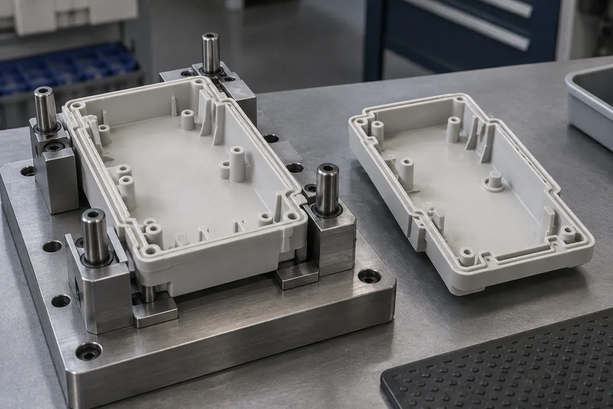
The final release package should state which requirements are closed, which are outside the supplier's scope and which remain open. An open system-level test is not automatically a molding defect, but it is not a completed qualification either. Making that distinction explicit protects both purchasing and engineering from an ambiguous promise.
Turn the review into a defined molding scope
Explore our custom molded connector insulators and terminal carriers and the related illustrative engineering study. Send the drawing revision, counterpart details, intended use and the decisions still open. Development samples and production approval should have separate, agreed deliverables.