
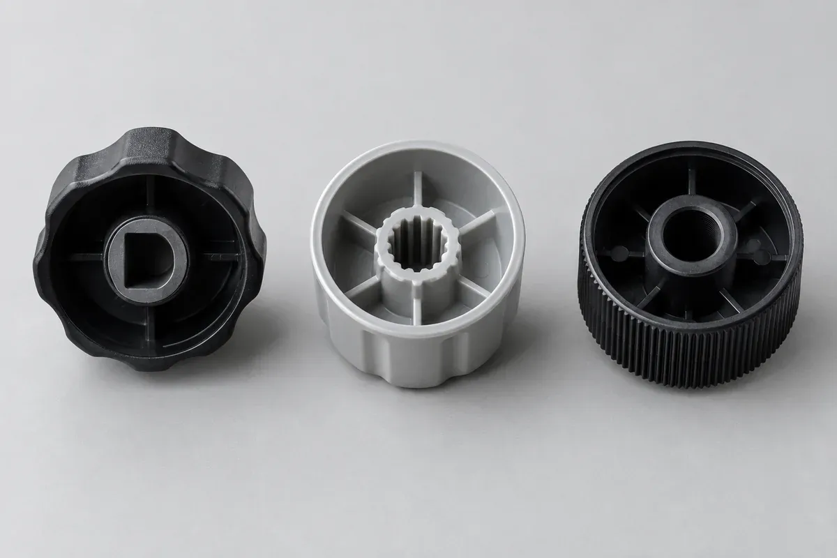
Product design illustrations. Final geometry, materials and acceptance criteria are project-specific.
A control knob described as fitting a particular shaft diameter may still be completely wrong for the assembly. The flat, spline form, engagement depth and retention method can matter as much as the nominal diameter. The visible pointer adds another requirement: it must indicate the intended angular position.
For a custom molded knob, request the shaft drawing or a controlled counterpart model before developing the bore. Photographs can help explain an existing problem, but they rarely establish the dimensions and angular relationships needed to release tooling.
Separate torque transfer, retention and indication
Three functions are often bundled into the word fit. The interface must transmit the specified operating torque, keep the knob in its intended axial position and align its index with the control state. A design can satisfy one of these while failing another.
Write those requirements separately. Identify the operating component and any limits on forces applied to its shaft. A knob that is difficult to install should not be forced onto a sensitive control merely because the plastic part itself appears strong enough.
Also define the gap to the panel and the available rotation envelope. A correctly formed bore can still leave the skirt rubbing the panel or place the user's grip too close to an obstruction. Assembly geometry belongs in the same review.
Describe a D-shaped interface completely
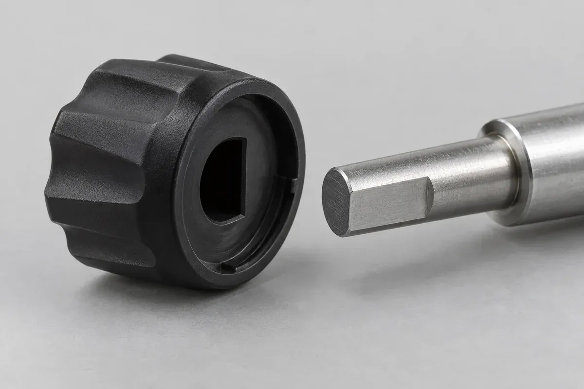
A D-shaft provides a flat that can establish angular orientation. Its usefulness depends on the actual mating geometry and permitted movement. Define the shaft's flat and the knob's matching bore, including the reference used to locate the visible index feature.
Consider the lead-in and the transition at the end of the shaft's usable section. The knob must engage the intended region without bottoming on a feature that was not meant to locate it. Mark the required assembled position on the drawing.
The related D-shaft indexing study follows these relationships through an illustrative assembly. It proposes a review method rather than a universal fit dimension or a verified torque rating.
Do not identify a spline by its tooth count alone
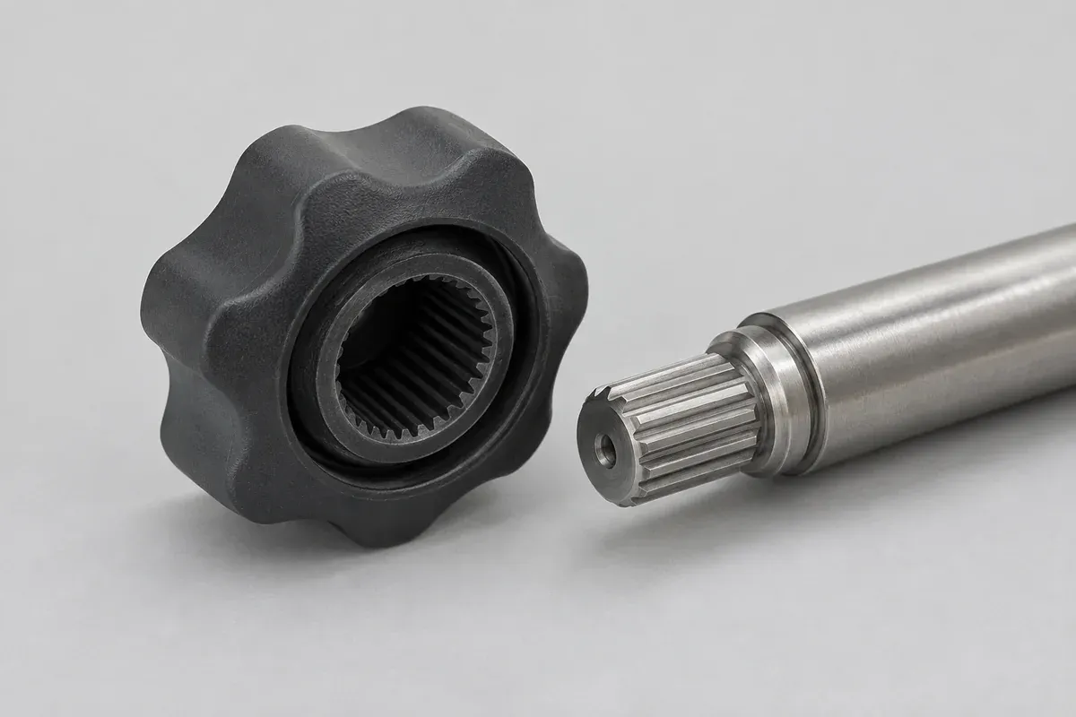
A splined or serrated interface needs its actual profile definition, size and engagement requirements. Matching the approximate tooth count from a photograph does not prove compatibility. Use the control manufacturer's drawing or an approved reference specification where available.
Discuss whether the design intentionally allows more than one angular installation position. If the visible mark has to align with a defined state, assembly instructions or a keyed feature may be needed. That requirement should be decided before the decorative face is finalized.
Keep the molding and inspection approach connected to the profile. Fine internal features require a tooling review and a suitable acceptance method. A nominal CAD match alone cannot show whether an actual molded sample engages the selected shaft as intended.
Specify how a round interface resists motion
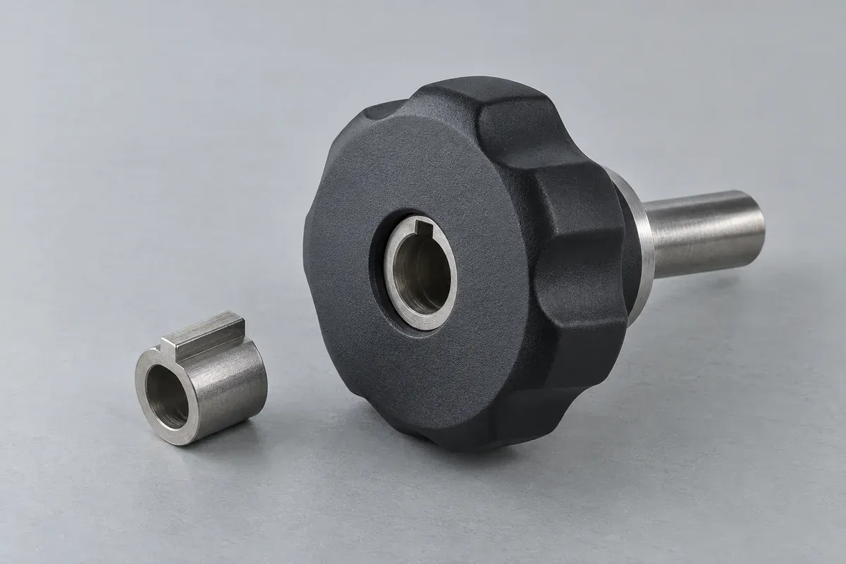
A round bore needs a defined strategy for transmitting torque and retaining the knob. Depending on the design, that may involve a clamping arrangement, set screw, insert or controlled interference. The choice affects the surrounding plastic geometry and the assembly process.
The press-fit versus set-screw comparison explains the procurement trade-offs. If a metal insert is involved, define its orientation and support rather than treating it as an unspecified accessory added after the plastic design is complete.
Ask how service removal will work. A permanently tight fit may conflict with a requirement to replace the control without damaging its shaft or panel. Installation and removal are separate use cases and should both be represented in the review.
Approve the assembly, not just the bore
Use identified knob and shaft samples with controlled revisions. Check axial seating, panel clearance, angular indication and the agreed functional behavior. Record the assembly method and specimen condition so the result is not dependent on undocumented hand adjustments.
Keep dimensional acceptance and performance tests distinct. A sample that fits is useful evidence, but it does not establish every torque, pull-off or life requirement. Those checks need their own conditions and criteria before production approval.
For a quotation, supply the knob design together with the shaft, panel and intended operating range. That interface package gives the molding supplier a defensible scope and reduces the risk of producing an attractive control that does not work in the actual assembly.
Turn the review into a defined molding scope
Explore our custom injection-molded control knobs and the related illustrative engineering study. Send the drawing revision, counterpart details, intended use and the decisions still open. Development samples and production approval should have separate, agreed deliverables.