
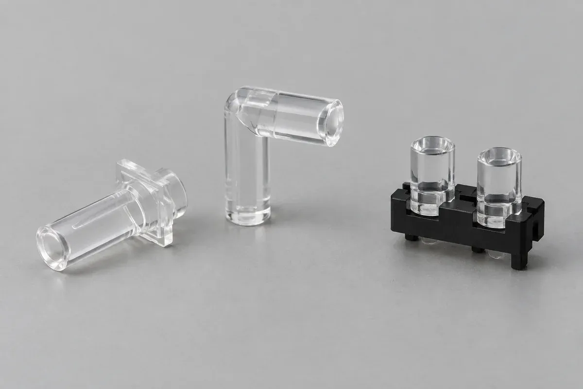
A status LED is easy to see on an uncovered circuit board. Put the board inside its enclosure and the problem changes: the user needs to recognize that status at a particular opening, from a useful viewing direction, without seeing light from a neighboring indicator. The light pipe connects those requirements to the board layout.
Select the optical route and the mounting reference together. A clear part that reaches both endpoints is not automatically a workable light pipe. Its entrance must remain aligned with the LED, its exit must fit the panel, and the assembly must retain those relationships without pressing the plastic against the LED package.
Product design illustrations. Final geometry, materials and acceptance criteria are project-specific.
Begin with the assembly, not the catalog diameter
Place the LED package, populated-board envelope, enclosure and front panel in the same controlled assembly. Identify the intended indication point and the space available between it and the source. Include cable connectors, tall components and the route by which the board is installed. A clear path in a section view may be obstructed during assembly.
Bivar's light-pipe selection guidance emphasizes considering the LED, mechanical space and viewing requirements early. For a custom molding project, turn that advice into named inputs: source package, board position, panel position, required indication area and allowable mounting changes. These are useful quotation inputs before a final optical geometry exists.
Separate what the user must recognize from how bright the indicator looks on a bench. A small on/off point, a broad illuminated symbol and a color-coded status window impose different requirements. Specify the relevant operating states and viewing conditions before choosing an exit shape merely because it looks attractive.
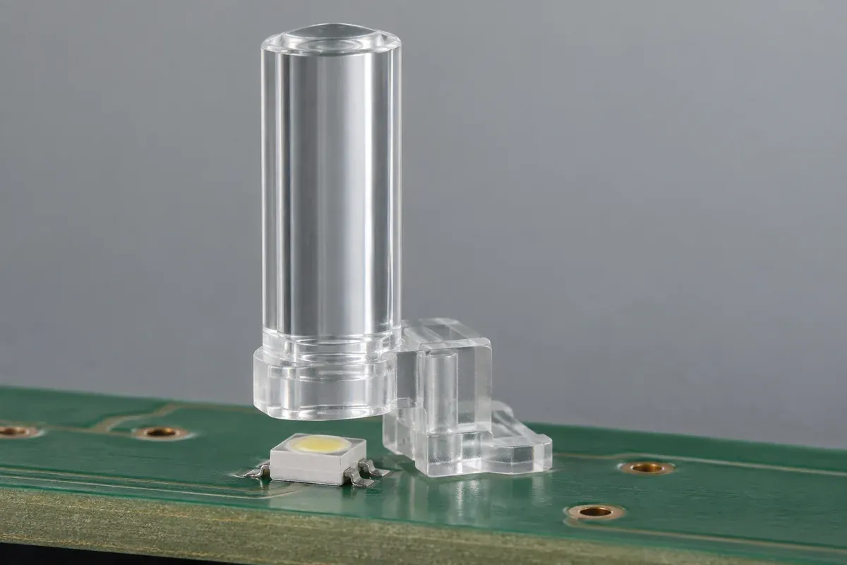
Choose a route that can be located and molded
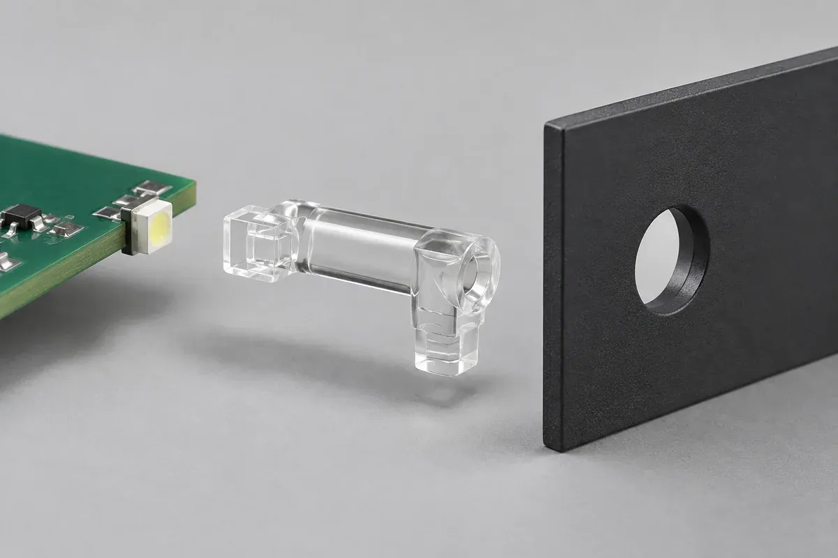
A straight rigid guide is a useful candidate when the LED faces the panel and there is a direct route between them. A right-angle guide can serve a board whose LED faces a different direction from the display. Neither description defines a finished optical design: cross-section, transition geometry and the source's angular distribution still matter.
For a tight or changing route, a flexible optical-fiber assembly may be worth comparing. That is a different supply and assembly route from the custom rigid injection-molded components discussed here. Do not force an elaborate molded shape into a design that a standard component or an alternative layout can satisfy more simply.
| Route | Useful starting condition | Question to resolve |
|---|---|---|
| Straight rigid guide | LED and display opening face each other. | Can the mounting hold both the entrance clearance and exit position? |
| Right-angle rigid guide | Source and panel face different directions. | Is there room for the transition, mold release and installation motion? |
| Multiple indicator guides | Several separately meaningful statuses share a panel. | How are channels located and unwanted light paths interrupted? |
| Alternative flexible assembly | The optical route must pass around obstacles. | Does its separate mounting and supply scope better suit the enclosure? |
Decide which part establishes the position
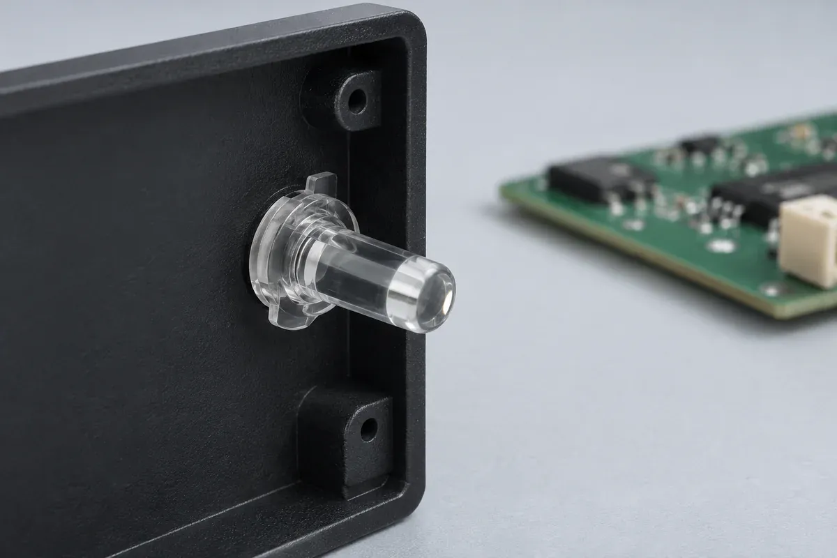
A board-mounted guide locates relative to PCB features. Its relationship to the LED can be relatively direct, while the panel opening remains part of a longer assembly chain. A panel-mounted guide reverses that emphasis: the visible exit is referenced to the panel, but the board-to-panel relationship now affects the entrance.
Neither is universally better. Consider which interface is most sensitive and which components are controlled together. Mounting a part rigidly to both the board and panel can introduce an unwanted constraint if those parts move relative to one another. Determine whether the intended design needs a defined float, a compliant retention feature or a different reference scheme.
Retention is not the same as location. A clip may keep a guide from falling out while allowing movement that changes its optical coupling. A close-fitting locating feature may establish position but be unsuitable for carrying installation force. Label those functions on the drawing rather than expecting one feature to solve both by accident.
Keep the entrance clear of mechanical loads
The LED is a source, not a stop for setting light-pipe height. Establish the intended clearance from the source and guide requirements, then check the full assembly variation. Include board position, LED package height, seating features and any panel movement that can reach the guide.
Check the installation sequence as well as the final position. A guide that clears the LED after assembly can still strike it while a panel slides into place. Our gap and offset review separates the nominal geometry from the movement and variation that must be evaluated.
Do not confuse a close fit with a seal
A flange sitting neatly against a panel does not establish an ingress-protection rating. Sealing materials, contact geometry, assembly load and the finished enclosure require a separately agreed evaluation when protection is needed. The same boundary applies to electrical or safety-related performance claims.
For several indicators, look beyond the visible face. Light can reach a neighboring window through the entrance area, a connecting transparent feature or space inside the enclosure. Decide whether separate guides and an opaque carrier deserve comparison; see the indicator crosstalk guide before treating an array as one simple clear molding.
Finally, compare a suitable catalog part with the proposed custom geometry. Dedicated tooling is justified by a defined requirement, not by the word custom. Record which source, panel and mounting features must stay fixed, which can change, and how the finished indication will be accepted. Those decisions make the molding quotation meaningful and reduce the chance that a late optical problem becomes an enclosure redesign.
Turn the review into a defined molding scope
Explore our custom injection-molded LED light pipes and the related illustrative engineering study. Send the drawing revision, counterpart details, intended use and the decisions still open. Development samples and production approval should have separate, agreed deliverables.