
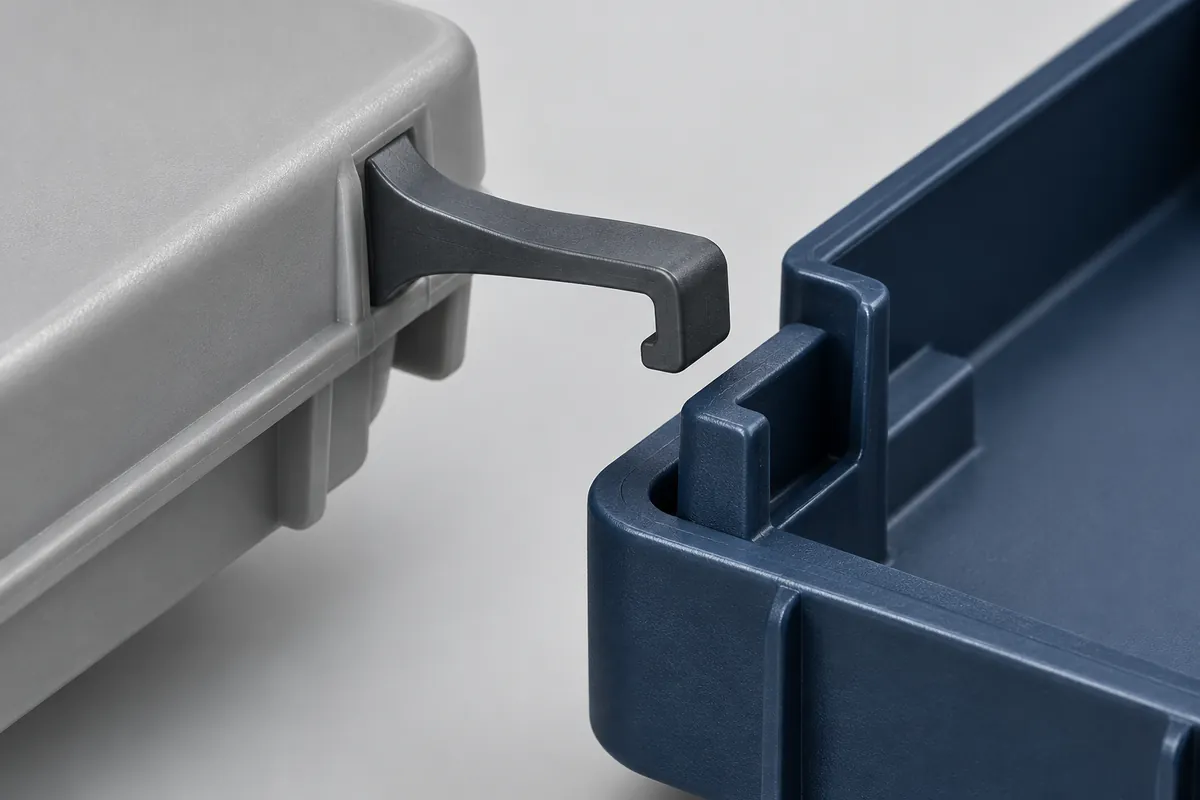
A removable cover can look finished in CAD while its latch remains an unresolved mechanism. The hook overlaps the receiving edge, so the assembly appears secure. But the model may not show how far the beam must bend during installation, whether the surrounding wall moves with it, or how a technician can release it later.
Review a cantilever snap-fit as a sequence of positions, not just a closed assembly. Establish the approach, maximum interference, engaged position and intended removal path before choosing beam dimensions. This article concerns integral molded clips for custom parts, not purchasing replacement trim fasteners from a catalog.
All images in this article are newly AI-generated illustrations of engineering concepts, not photographs of a customer project or evidence of completed testing.
Draw the Four Positions Before Editing the Beam
Start with a section through the actual engagement path. Show the two components apart, at their largest interference, seated and being released. Keep both components on the drawing. Looking only at the flexible clip can hide a receiving edge that is too thick, a cover that bottoms out early or a nearby wall that blocks deflection.
Mark the intended support surfaces and which component is expected to flex. If the cover wall also bends, a simple fixed-root beam model may not represent the assembly. BASF's snap-fit design application identifies beam geometry, engagement angles, deflection and material strain as calculation inputs. A calculation remains tied to its assumptions; it is not validation of an unreviewed assembly.
The interference should come from the mating geometry and tolerances rather than an arbitrary target deflection. Review the conditions that produce the greatest assembly displacement and those that produce the least remaining engagement. These can be different combinations of dimensions, and passing one condition does not establish the other.
A Longer Beam Changes More Than Assembly Feel
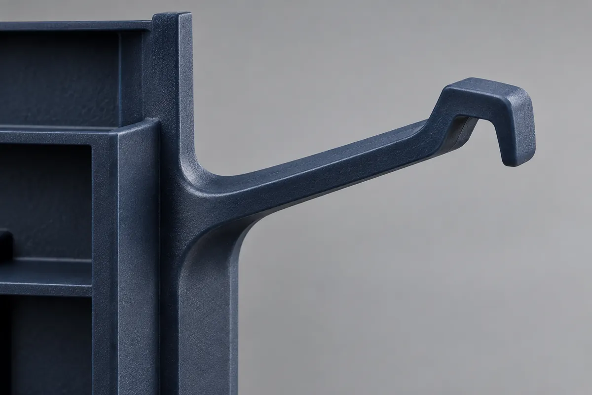
Suppose a conceptual equipment lid has a short latch trapped between a corner and a rib. Extending the flexible region is one candidate change; reducing the engagement interference is another. The first changes the space used by the mechanism. The second changes the overlap available to hold the cover. They are not interchangeable fixes.
Review the root transition, beam thickness profile and width together with the selected resin grade. Avoid selecting a fillet or a strain limit from an unrelated example and treating it as universal. The material condition, expected opening frequency and molded geometry matter. A room-temperature demonstration with one sample is useful feedback, but does not establish a repeated-use limit.
A relief slot can create room for a longer flexible region, but it may also open a path for dust, alter appearance or remove support elsewhere. The right drawing records those consequences. Our releasable clip design study compares two such concepts without assigning either a measured performance advantage.
Design the Release Operation Deliberately
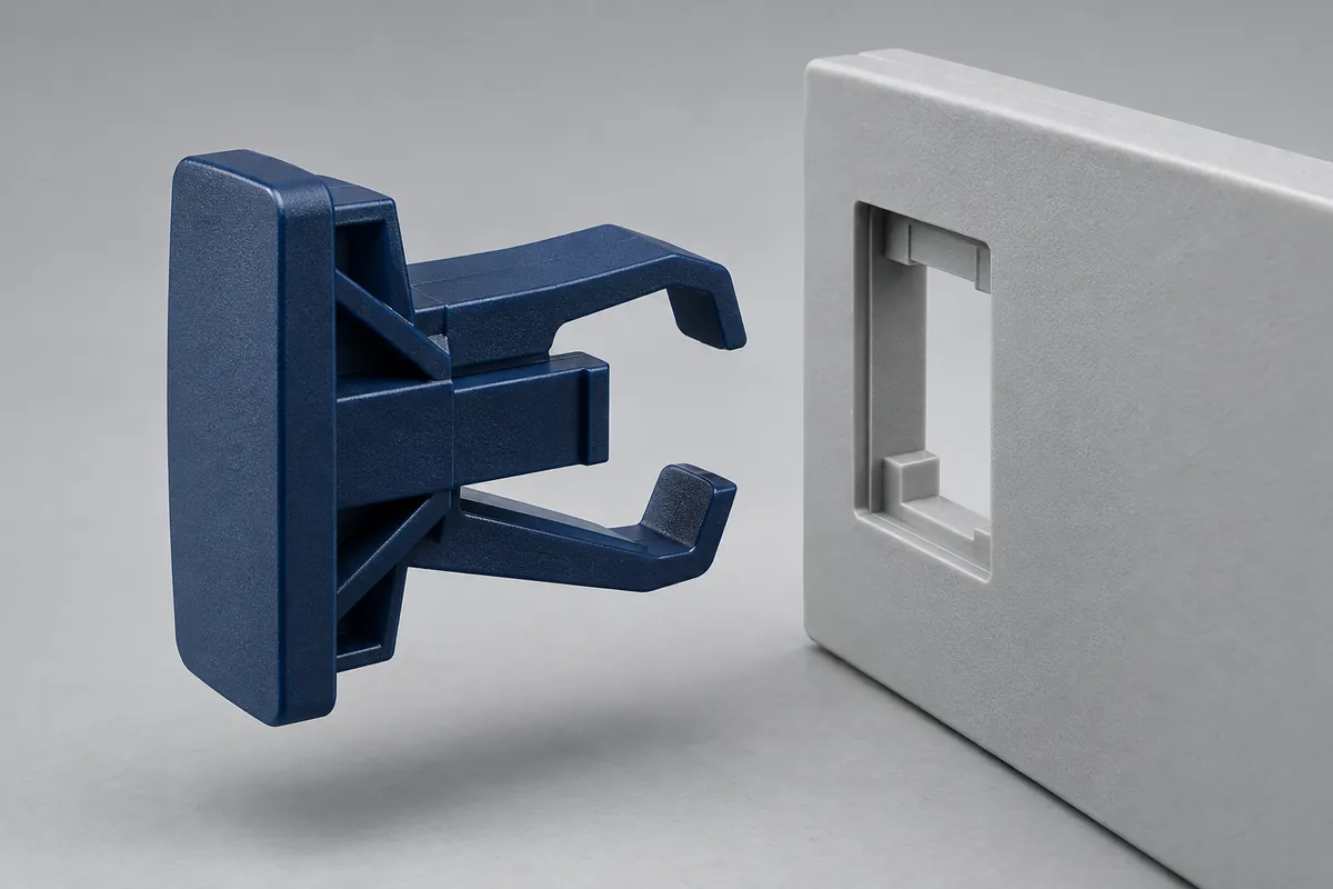
A clip intended for occasional service needs a reachable release feature. Ask whether the operator pushes the beam, pulls the cover, uses a specified tool or combines movements. If access disappears after adjacent equipment is installed, an attractive bench demonstration may not represent the service operation.
Separate deliberate release from accidental withdrawal. A latch can require little removal force after its tab is depressed while still resisting a pull when the tab is untouched. Putting both results under a single “removal force” heading creates ambiguity. Specify the action and the load direction beside each requirement.
Consider an over-travel stop where misuse could bend the arm beyond its intended path, but review the stop's own contact and load path. Adding a stop is not proof that damage has been prevented. The assembly and release checks should include the relevant surrounding parts, not a conveniently isolated clip.
Turn the CAD Review into a Controlled Decision
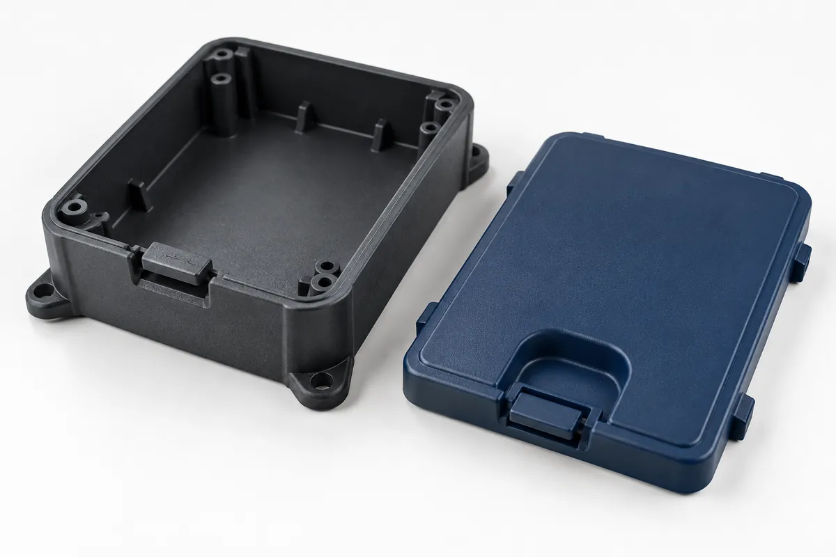
Record unresolved assumptions directly on the marked-up drawing: material grade, mating revision, permitted changes, tolerance combinations, release method and test owner. A supplier can then distinguish an approved interface from a concept that is still open to development. This avoids quoting tooling against a visually complete but functionally incomplete model.
Plan insertion and removal cycle testing separately from long-term retention under load. The former examines repeated operation; the latter examines behavior while engaged over time. Neither should be inferred from the sound or feel of the first snap.
For a custom injection-molded clip or retainer, the next useful step is a scoped design review, not a universal promise of force or life. Send the clip and mating-part drawings for a quote, including how it must assemble, stay engaged and come apart. Keep tooling approval dependent on closing the relevant design questions.