

| Gas assisted injection molding (GAIM) injects nitrogen gas at 2,000–4,500 psi into a partially filled mold cavity (70–90% resin fill), displacing molten plastic to create hollow internal channels. This reduces material use by 20–40%, eliminates sink marks, lowers clamp force by 25–60%, and allows variable wall thickness that conventional injection molding cannot achieve. |
Sink marks and warpage in thick-wall plastic parts are expensive problems. They surface after tooling is cut, they slow production, and they force compromises on part geometry that often outlast the original design intent. Gas assisted injection molding (GAIM) was developed specifically to solve these problems — and it does so by replacing the pack-and-hold pressure stage of conventional molding with pressurised nitrogen gas inside the part itself.
In the following article, we will talk about the gas assist injection molding principles and applications – what it is, the pros and cons of it, how it works, and what types of products benefit from it.
What Is Gas Assisted Injection Molding?
Gas assist injection molding originated in 1983 as the UK-developed ‘Cinpres’ process for structural foam building materials. After its showcase at the German International Plastics Machinery Exhibition in 1986, it was rapidly adopted across North America, Europe, and Japan. By the 1990s it had moved from experimental to production-standard, and it remains the preferred technique for thick-section structural plastic parts where weight, surface quality, and dimensional stability must all be achieved simultaneously .
The process combines standard thermoplastic injection with a precisely timed injection of high-pressure inert gas — almost always nitrogen — into the molten core of a partially filled mold cavity. The gas takes the path of least resistance through the hottest, least viscous plastic, forming a continuous hollow channel through the thickest sections of the part. As the gas expands, it pushes the remaining melt against the mold walls, completing the fill from the inside out.
Gas injection pressure typically runs between 2,000 and 4,500 psi (14–31 MPa), depending on the polymer’s viscosity and the wall thickness of the part. In high-pressure configurations the system can reach up to 35 MPa (standard) or 70 MPa (special cases). Nitrogen purity must be ≥98% — a lower-purity supply causes inconsistent penetration and part-to-part variation. [1]
The two parameters that define the gas injection are straightforward: gas injection time (seconds) and gas injection pressure (MPa). Everything else — where the gas travels, how far it penetrates, what hollow geometry it forms — is determined by the mold’s gas channel design and the short-shot ratio set by the process engineer.
What Gas Assist Injection Molding Process Solves?
In conventional injection molding, thick sections cool from the outside in. The surface skins first; the interior contracts as it cools; the surface is pulled inward, creating sink marks.
Pack-and-hold pressure can partially compensate, but once the gate freezes, no more pressure reaches the part interior. Gas pressure, by contrast, can be maintained throughout the entire cooling phase, applying uniform internal pressure until the part is solid. [2]
Advantages and Disadvantages of Gas Assisted Injection Molding
While there are many advantages of gas assisted injection molding, this process has some disadvantages. Let’s look at the pros and cons and see if it could be right for your project.
Advantages
Material savings: Hollow gas channels reduce resin consumption by 20–40% depending on part geometry. For a large structural panel, this is not a marginal saving — it directly cuts material cost per part and reduces the volume of plastic that needs to cool, which also shortens cycle time.
Lightweight Parts: By using gas to create hollow sections, you are using less plastic material. This makes the parts lighter in weight while maintaining strength. Use the example of a bone: strong on the outside and hollow on the inside.
Eliminated sink marks: The gas maintains uniform pressure against the mold walls throughout cooling. The mechanism that causes sink marks — differential contraction between a cooled surface skin and a still-fluid interior — is directly counteracted. Ribs, bosses, and thick-wall transitions that would be high-risk in conventional molding become producible without cosmetic compromise.
Reduced clamp force: Because the gas distributes pressure evenly through the hollow channel rather than requiring high pack pressure at the gate, clamp force requirements drop by 25–60% compared to conventional molding for equivalent parts. This allows larger parts to run on smaller machines.
Design freedom: Variable wall thickness — impossible in conventional molding without accepting sink risk — becomes controllable. Large unsupported sections, structural ribs, and complex cross-sections can be designed without being constrained to uniform wall thickness. Parts that would require multiple components bonded together can often be consolidated into a single gas-assisted shot.
Cycle time improvement: Hollow cores cool faster than solid sections. The cooling phase, which typically accounts for 40–60% of total cycle time in thick-wall conventional molding, is shortened. This improvement scales with wall thickness — the thicker the section, the greater the cycle time benefit.
Disadvantages
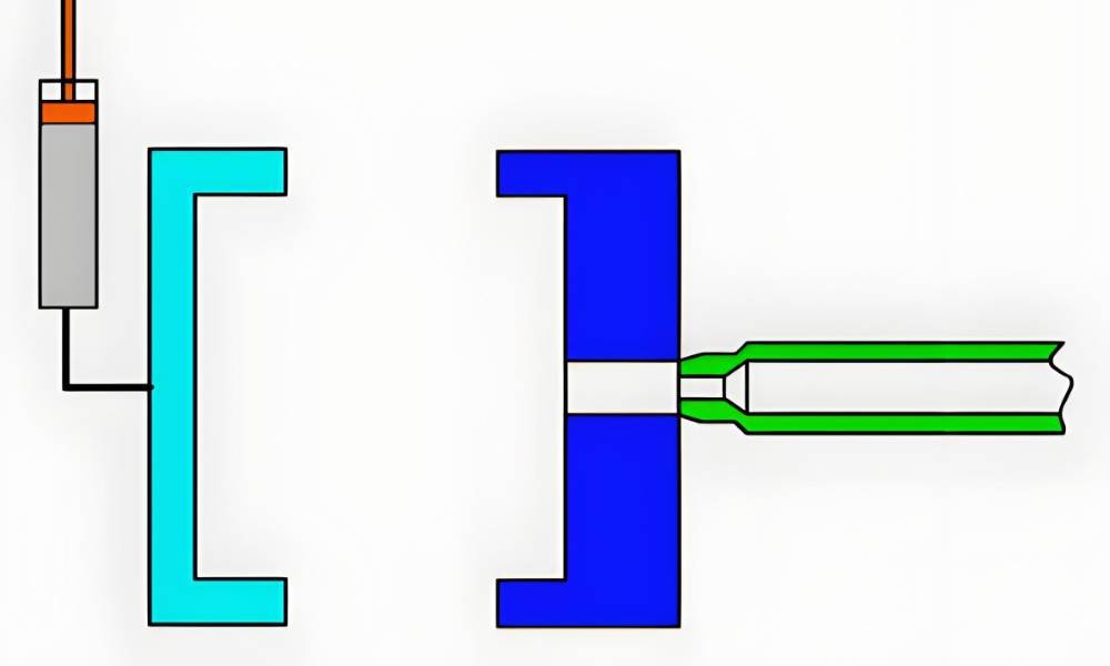
Higher tooling investment: Gas pins, gas channels, and the separate gas-assist control unit add cost relative to a standard injection mold. The control unit is an independent system connected to the injection machine only by an injection signal line. For small production volumes or simple part geometries that don’t require gas assist, this investment won’t pay back.
Complex mold design: Gas channel placement is a DFM decision, not an afterthought. The channels must be sized and routed to guide the gas through thick sections without dead ends, while keeping the gas away from thin walls that the gas would blow through. Getting this wrong produces inconsistent hollow geometry, short fills, or gas breakthrough at the part surface.
Gas marks (blushing): When gas contacts the mold surface prematurely — usually due to a thin wall section, a misplaced gas channel, or excessive gas pressure — it leaves a visible surface mark. The root cause is almost always gas channel design or process pressure exceeding the wall’s ability to contain the gas. The fix is reducing gas pressure in the affected zone, repositioning the channel entry point, or adding a local wall thickness increase at the breakthrough location.
Process expertise required: GAIM has two additional process variables that don’t exist in conventional molding — gas injection time and gas injection pressure. Both interact with the resin’s viscosity, the part geometry, and the mold temperature. Dialling in these parameters requires experience. Running excessive hold pressure from the injection machine simultaneously blocks gas penetration and risks a blowout when the mold opens [2].
GAIM vs. Traditional Injection Molding: Parameter Comparison
The table below compares the two processes across the parameters that typically drive the tooling and process selection decision.
| Parameter | Gas-Assisted (GAIM) | Traditional Injection Molding |
| Melt fill level | 70–90% of cavity (short shot) | 100% (full shot) |
| Packing mechanism | Nitrogen gas at 2,000–4,500 psi | Screw back-pressure (high hold pressure) |
| Clamp force required | 25–60% lower | Full clamp force needed |
| Material usage | 20–40% reduction possible | Full part volume of resin |
| Sink mark risk | Eliminated — gas pressure prevents differential cooling | High in thick-wall sections |
| Cycle time (thick parts) | Shorter — hollow core cools faster | Longer — solid mass requires full cooling |
| Part weight | Lighter — hollow channels | Full solid weight |
| Wall thickness range | 2–6 mm supported | Uniform thin wall preferred |
| Design complexity | Complex geometries, variable wall | Best for uniform wall thickness |
| Initial tooling cost | Higher — gas pins, gas channels required | Standard tooling |
Two Types of Gas Assisted Molding
There are two main types of gas assisted molding, and each has its own unique application. Let’s take a look at both.
Internal Gas Assisted Molding
Process: Gas is injected directly into the molten plastic core through a gas pin positioned at the nozzle or within the mold cavity. The gas expands as a bubble through the thickest sections of the part, forming a continuous hollow channel. It holds pressure from the inside outward while the outer skin cools and solidifies against the mold walls.
Wall thickness range for internal GAIM: typically 4–6 mm or greater at the gas channel locations, tapering to the required outer wall thickness. The gas naturally follows the path of least resistance — hottest, lowest-viscosity plastic — which must align with the designed gas channel route. If the short-shot ratio is too low, the gas finds the route before the resin has fully packed the edges; if too high, there’s insufficient material for the gas to displace.
Benefits: This method is ideal for making lightweight parts with thin walls. The amount of shrinkage and warpage is less, and because the gas is applying pressure from the inside outwards, it reduces deformation as the part cools. You are left with a product that is strong, stiff, and with less material.
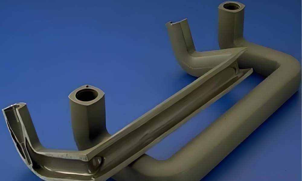
Applications: automotive instrument panels, door handles, furniture frames, chair arms, appliance handles, large structural housings. Any part where a structural frame or rib network needs to be hollow for weight or acoustic reasons.
External Gas Assisted Molding
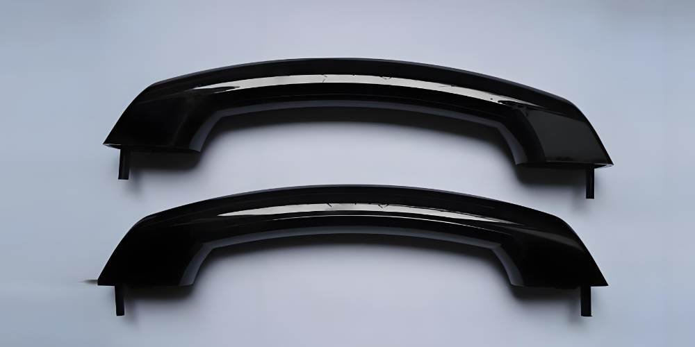
Process: Gas is introduced through microchannels on the non-cosmetic (back) face of the mold, applying pressure to the rear of the part rather than through its core. The gas does not create a hollow channel — instead it acts as a uniform pressure pad that pushes the front cosmetic surface hard against the mold wall throughout cooling.
Primary purpose: Enhance surface quality on large cosmetic panels. Where internal GAIM solves structural and weight problems, external GAIM solves sink marks on the A-surface of parts with ribs and bosses on the B-side. The rib geometry creates thick-section regions that would normally pull the cosmetic surface inward as the part cools; external gas pressure on the back face counteracts this.
Benefits: This method is great for parts with complex surface patterns as well as large, complex curves. It can also work for thick sections without defects. The gas pressure helps reduce sink marks on the surface of the parts, which is beneficial when creating aesthetic components.
Applications: automotive dashboards and door panels (where A-surface quality is critical), large appliance front panels, consumer electronics back-shells. Parts where the hollow core of internal GAIM isn’t needed but the surface quality of conventional molding isn’t sufficient.
How Gas Assisted Injection Molding Works: Step by Step
The process runs as a timed sequence. Each step’s parameters interact — the short-shot ratio of step 1 determines how much room the gas has in step 2; the gas hold time in steps 2 and 3 determines whether the part cools with consistent internal pressure.
- Plastic resin injection (short shot): Molten thermoplastic fills the cavity to 70–90% of its volume. The exact fill ratio depends on the part geometry and the target hollow percentage. Larger gas channels need a lower fill ratio to give the gas room to penetrate; complex geometries with thin outer walls need a higher ratio to ensure the resin reaches extremities before gas injection begins.
- Primary gas penetration: High-pressure nitrogen — typically 2,000–4,500 psi — is injected into the melt immediately once the fill reaches the target level. Timing is critical: any delay allows the melt front to cool and increases viscosity in the channel, making the gas work harder to penetrate. The gas forms a bubble in the thickest section and expands outward, pushing the melt to fill remaining extremities.
- Secondary gas penetration (gas hold): As the resin cools and contracts, the gas continues flowing into the part to compensate for volumetric shrinkage. This is the phase that replaces pack-and-hold in conventional molding. Gas hold time is typically 5–10 seconds. The gas pressure maintains the outer surface in contact with the mold wall throughout, preventing sink marks from forming.
- Gas venting and ejection: All gas must be fully vented from the cavity before the mold opens. Failure to vent causes the hollow section to expand when mold pressure is released — in extreme cases the part can burst. The gas exits through the same pin used for injection, or through a separate vent pin, back through a sprue break. Once vented, the mold opens and the part ejects.
DFM Considerations for Gas Assisted Injection Molding
Getting the mold design right for GAIM requires addressing several considerations that don’t arise in conventional injection molding:
- Gas channel sizing: Channels should be located in the thickest sections of the part. A channel cross-section of at least 6 mm diameter is generally needed for reliable gas penetration; smaller channels increase resistance and produce inconsistent hollow geometry. Channels must not dead-end — gas needs a route through the entire thick section.
- Short-shot ratio: The fill level at which gas injection starts determines the hollow percentage and the outer wall thickness. Too low a fill ratio and the gas will blow through thin walls or not reach the extremities of the mold. Too high and there is insufficient material for the gas to displace, reducing the hollow benefit.
- Wall transition gradients: Abrupt transitions between thick gas-channel sections and thin outer walls create stress concentrations at the junction and increase the risk of gas breakthrough. Gradual tapers from the gas channel diameter to the outer wall are preferred.
- Gate placement: The gate should be positioned to fill the outer extremities of the mold with resin before the gas begins penetration. If gas reaches a dead end (an area the resin hasn’t reached yet), it voids out with no plastic wall, producing a defective part. Gate placement and gas channel routing must be designed together.
- Hold pressure setting: Injection machine hold pressure must be kept low (or off) during gas injection. High hold pressure blocks the gas pin, traps gas in the cavity (blowout risk on mold opening), and hinders gas penetration — producing the sink marks the gas was meant to prevent [3].
Plastic Materials for Gas Assisted Injection Molding
GAIM is compatible with most thermoplastics, but material selection affects gas channel sizing, penetration behaviour, and the resulting hollow geometry. The table below summarises the common materials and their GAIM characteristics.
| Material | Melt Strength | Viscosity | Best GAIM Applications |
| PP (Polypropylene) | Low | Low viscosity | Instrument panels, containers, automotive interior trims |
| ABS | Medium | Medium | Electronics housings, consumer appliance panels, toys |
| PC (Polycarbonate) | High | Medium-high | Safety equipment enclosures, transparent structural components |
| HDPE | Low | Low-medium | Outdoor furniture, pipes, heavy-duty containers |
| HIPS | Low-medium | Low | Consumer packaging, display items, thin-wall trays |
| Nylon (PA) | High | Medium (dry) | Gears, structural brackets, sports equipment, load-bearing parts |
A note on melt flow and gas penetration: materials with high melt flow index (MFI) allow gas to penetrate more freely, which is generally beneficial but requires tighter timing control — the gas can over-penetrate into thin sections if injection timing is not precise. High-viscosity materials like PC require higher gas pressure to achieve the same penetration depth at equivalent wall thickness.
Applications of Gas Assisted Injection Molding
Automotive
Instrument panels, door panels, seat backs, and A-pillar trims are produced with GAIM because the process delivers the structural rigidity of a thick cross-section at the weight of a hollow one. Reducing weight in interior trim directly affects fuel efficiency and increasingly electric range — a measurable benefit at scale. External GAIM is commonly applied to dashboards where A-surface quality is non-negotiable.
Consumer Products
Furniture components — chair arms, table legs, storage unit frames — are a natural fit for internal GAIM. The hollow channel provides the stiffness-to-weight ratio of a structural extrusion without the secondary joining operation. Vacuum cleaner housings, appliance bodies, and power tool housings benefit from GAIM’s ability to produce complex geometries with varying wall thickness in a single shot.
Electronics
Electronic enclosures require dimensional stability (no warpage) and a defect-free cosmetic surface. GAIM delivers both by eliminating the differential cooling that causes both problems in thick-wall conventional molding. For large back-shells and structural chassis, the weight saving is an additional benefit for portable devices.
Aerospace
Interior panels, air duct sections, and seat frame components all benefit from GAIM’s weight reduction. In aerospace, weight savings from structural plastic components translate directly to operational cost reductions. The process also allows these parts to be produced to tight dimensional tolerances without the warpage that would otherwise require secondary straightening operations.
Frequently Asked Questions
What gas is used in gas assisted injection molding, and why nitrogen?
Nitrogen (N₂) is the standard choice because it is inert — it does not react with the polymer melt at injection temperatures. Purity must be ≥98% for consistent results. Lower-purity nitrogen introduces moisture and other gases that cause irregular penetration and surface defects. The gas is delivered by either a dedicated nitrogen generator or high-pressure cylinders, through a gas-assist control unit that regulates injection timing and pressure.
What pressure is used in gas assisted injection molding?
Gas injection pressure typically runs between 2,000 and 4,500 psi (14–31 MPa) for standard applications, depending on the polymer viscosity and wall thickness. The system can reach up to 35 MPa in standard configurations and 70 MPa in high-pressure special cases. Two values control the process: gas injection pressure (MPa) and gas injection time (seconds) — everything else is determined by the mold design.
How much material does gas assisted injection molding save?
Hollow-core GAIM designs can reduce material usage by 20–40% compared to an equivalent solid conventional part, depending on the hollow percentage achievable for the part geometry. This saving compounds at volume: for a large structural panel running at 100,000 parts/year, a 30% material reduction is a significant annual cost saving on resin alone.
What is the difference between internal and external gas assisted molding?
Internal GAIM injects gas into the molten core of the part, creating hollow channels through thick sections. It is used for structural parts where weight reduction and sink mark elimination are both required. External GAIM applies gas pressure to the back face of the part (not into its core) to push the cosmetic front surface against the mold wall during cooling. It is used for large cosmetic panels where surface quality is the primary concern but a hollow core is not needed.
What wall thickness range does GAIM support?
Parts produced with gas assisted injection molding typically have outer wall thicknesses from 2 to 6 mm, with gas channel cross-sections sized to at least 6 mm to enable reliable gas penetration. Walls thinner than 2 mm at the gas channel location risk gas breakthrough; walls thicker than 8–10 mm at the channel may not achieve consistent hollow geometry without careful pressure and timing calibration.
When should you choose GAIM over conventional injection molding?
GAIM is the better process when: the part has wall sections thicker than 4–5 mm that would cause sink marks in conventional molding; the part design requires variable wall thickness; weight reduction is a design requirement; the part is large enough that reduced clamp force requirements allow it to run on a smaller machine; or surface quality on a cosmetic face with opposing ribs/bosses cannot be achieved conventionally. GAIM adds tooling cost — if the part is thin-walled and uniform, conventional molding remains the simpler and cheaper option.
Conclusion
Gas assisted injection molding solves the specific problem that conventional injection molding cannot: producing thick-wall plastic parts with controlled hollow geometry, defect-free surfaces, and reduced weight — in a single production step. The gas does the work that pack-and-hold pressure cannot: it reaches every thick section of the part, maintains uniform pressure throughout the cooling phase, and compensates for thermal contraction from the inside out.
The process parameters are simple in number — gas injection pressure and gas injection time — but the DFM decisions that determine where those parameters take effect require engineering expertise. Gas channel design, short-shot ratio, gate placement, and hold pressure settings all interact. Getting them right produces parts that conventional molding cannot match; getting them wrong produces expensive scrap.
At Fecision, our injection molding capability covers gas-assisted processing for precision structural plastic parts. Our engineering team handles the DFM stage — gas channel routing, short-shot optimisation, and process parameter development — as part of the tooling programme. Contact us for a DFM review if you’re evaluating GAIM for a specific part design.
References & External Citations
All sources publicly available. Accessed April 2026.
[1] Onex Machinery. ‘The Application and Process of Gas-Assisted Injection Molding Technology.’ (Jan 2025) https://onexmachinery.com/the-application-and-process-of-gas-assisted-injection-molding-technology/
[2] Bauer Compression. ‘The Process of Gas Assist Injection Molding.’ (Technical white paper) https://www.bauercomp.com/sites/default/files/uploads/The_Process_of_Gas_Assist.pdf
[3] Wikipedia. ‘Gas-Assisted Injection Molding.’ (Sep 2025) https://en.wikipedia.org/wiki/Gas-assisted_injection_molding


