
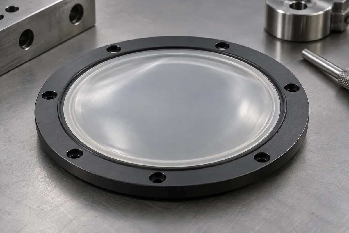
Product design illustrations. Final geometry, materials and acceptance criteria are project-specific.
Membrane thickness is an important diaphragm dimension, but it does not describe the working strain by itself. A thin membrane with generous transitions may move differently from a thicker membrane forced around a sharp edge. The useful design question is where the material deforms throughout the required stroke.
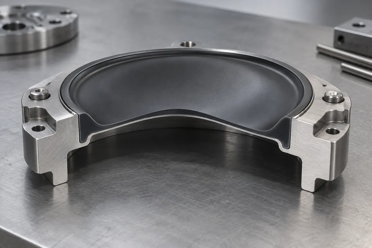
Begin by separating the active membrane from the clamping flange and any central attachment. These regions have different functions and often need different sections. Making the whole part uniformly thicker can change sealing compression, actuation force and available movement without solving the original failure mechanism.
Map the moving span
Show the unsupported span and the contact surfaces at several positions. Where the membrane meets a rigid feature, the transition can become a repeated bending location. A small geometry change there may matter more than a modest increase in thickness across a broad, gently moving area.
Specify whether stroke means total movement or travel from the neutral position in one direction. Confusing these definitions can double the displacement used in a design review. Include the end stops and any permitted overtravel, because the real mechanism may not stop exactly at its nominal command position.
Diaphragm suppliers discuss geometry and operating conditions together in their life-design guidance. Treat such guidance as a prompt to examine the assembly, not as a formula that converts one wall dimension into a guaranteed cycle count.
Do not replace geometry with hardness
Shore hardness is a material characterization, not a direct measure of diaphragm spring rate. The molded shape, thickness distribution and boundary conditions contribute to force response. Two parts made from nominally similar hardness grades can behave differently if one has a shorter flexible span or a tighter transition.
Compare exact compounds where fluid exposure or temperature matters. Changing the formulation to obtain a different hardness can also change other properties and processing requirements. Record the grade and cure condition used in the sample rather than assuming every silicone at the same hardness is interchangeable.
If simulation is used, state the material model, contact assumptions and boundary conditions. A colorful stress plot without these inputs is not a validation result. Use physical measurements to check whether the model reproduces the observed displacement and force before relying on it to rank detailed changes.

Control what the inspection can actually resolve
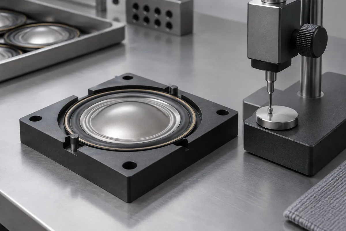
Soft thin sections can deform under a measuring contact. Agree the instrument, contact force and location before interpreting small differences between suppliers. A method suitable for a rigid plastic wall may compress a flexible membrane enough to change the reading that appears on the report.
Sample across cavities and meaningful locations. A center reading alone can miss a thin transition or an uneven flow-related distribution. Identify each reading in relation to the part drawing so an outlying result can be investigated instead of being averaged into an apparently acceptable thickness.
Define which condition is inspected: free state, supported state or assembly state. The dimensions of a flexible part held in an arbitrary fixture may not be comparable with a free-state drawing. Keep the measurement method attached to the acceptance requirement rather than leaving it as an informal shop practice.
Validate the duty cycle
Use representative molded parts for functional testing and record both the measured geometry and process identity. If a thickness change improves one test, check its effect on sealing, force and assembly. A design improvement should not be judged from a single response while another requirement silently becomes worse.
Plan pressure-cycle and fatigue evaluation with explicit stop criteria. Record interim observations as interim observations. Surviving part of a planned endurance run does not establish completion of the target or predict the life of every production part.
The final drawing should connect thickness tolerances to a practical inspection method and an approved assembly. That makes subsequent material, tool or housing changes reviewable against a known baseline instead of turning thickness into an isolated number with uncertain functional meaning.
Discuss the component and its acceptance requirements
Explore our custom silicone diaphragms and the related project case study. Send the current drawing, mating-part details, operating conditions and required quantities. We can review tooling, molding and inspection as a defined supply scope, with development samples and production approval kept separate.