
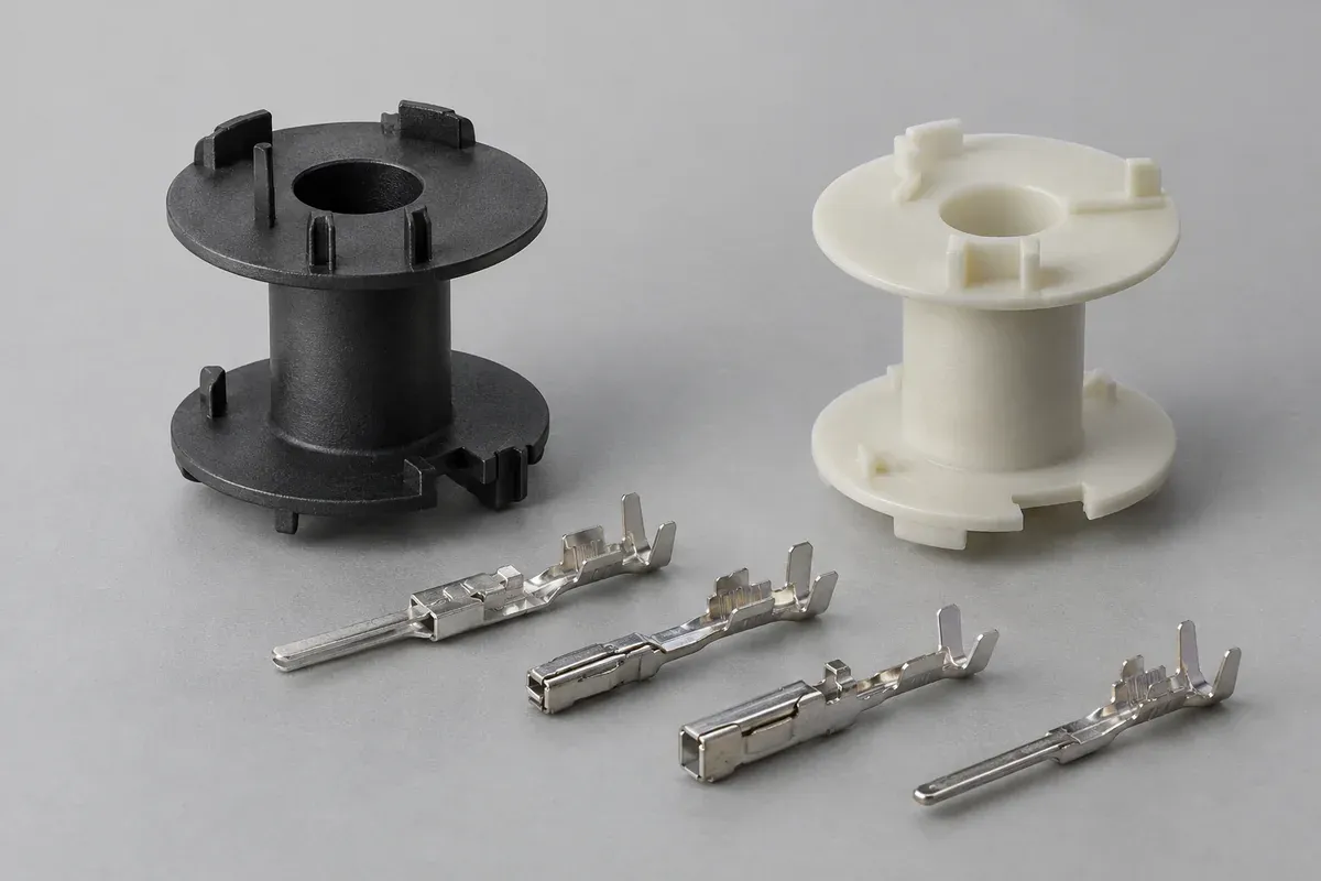
Product design illustrations. Final geometry, materials and acceptance criteria are project-specific.
A coil bobbin with pins can be supplied through different manufacturing routes. Pins may be positioned in the mold before plastic is injected, or installed into defined features after the plastic component is molded. Both routes need a controlled terminal specification and an agreed inspection plan.
The choice is not simply fewer operations versus more operations. It changes how the pins are located, how their surfaces are protected, what the tool must accommodate and which operation establishes final position. Compare those responsibilities before comparing unit prices.
Define the terminal before choosing its process
Specify the terminal geometry, material, finish, engagement region and features that interface with wire or the circuit board. State whether it is an existing controlled component or a custom item. Similar-looking pins can have different installation and connection requirements.
Identify the functional lengths and locations relative to the bobbin. The dimension that matters to a winding operation may differ from the one that matters to board insertion. Show both reference systems and their relationship in the assembly definition.
Keep terminal procurement in the commercial scope. A molding-only price cannot be directly compared with an offer that includes pins, handling, installation and inspection. If the customer supplies terminals, agree incoming acceptance and responsibility for rejected or damaged stock.
Review the molded-in locating arrangement
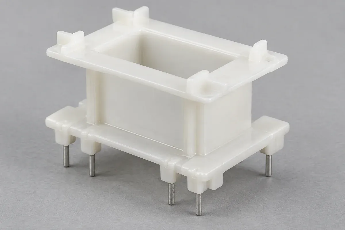
For insert molding, ask how the pins are seated and retained during the molding cycle. Tool features must establish the intended position while permitting loading and release. A terminal that appears correctly placed before molding still needs a finished-part positional check.
Discuss which pin surfaces may contact the tool and where plastic must stop. Unwanted plastic on a connection area can create a downstream problem even if the pin pitch is correct. Define those exclusion zones explicitly rather than relying on an informal sample photograph.
Consider how malformed, absent or incorrectly loaded inserts will be detected. The control method belongs in the process proposal and should fit the component and production scope. Do not assume that a general insert-molding capability includes every inspection method a particular terminal needs.
Review support and alignment for later installation
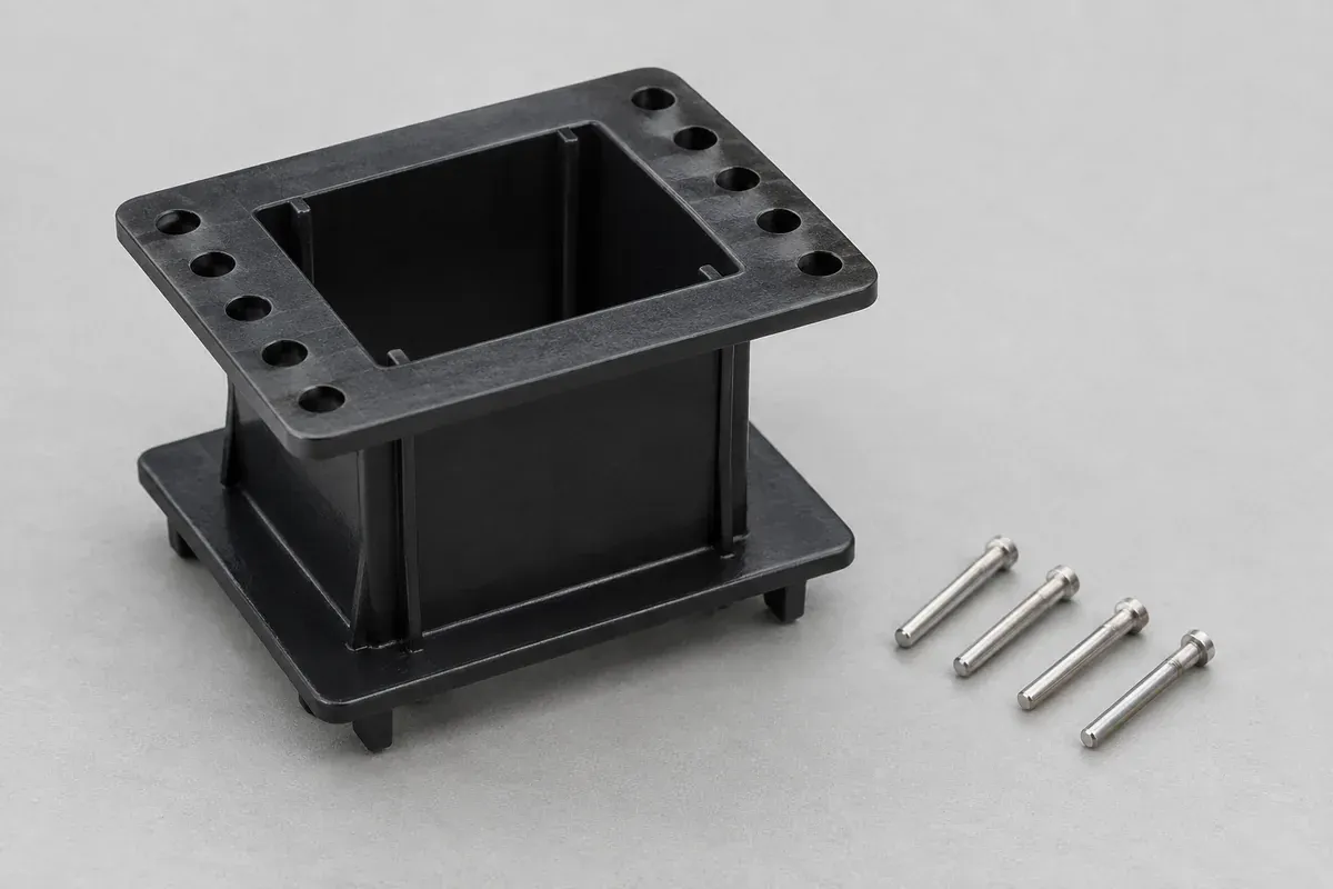
With post-installed pins, the molded receiving feature and the installation method form one system. Define the hole or retaining geometry, pin orientation, insertion direction and final position. These details should be reviewed together instead of being assigned to separate suppliers without a shared interface.
Support the plastic near the installation region using a suitable fixture concept. An unsupported flange may deflect during assembly, making a nominal insertion distance difficult to interpret. The fixture must not hide damage or constrain the final component differently from its inspection state.
Record the installation method and agreed process controls. If heat, ultrasonic energy or mechanical force is proposed, it requires validation for the actual terminal and resin. A generic process name is not an approved parameter set.
Separate retention from electrical connection quality
A pin remaining in the plastic during handling does not prove its connection performance after winding and termination. Define component retention checks separately from the electrical assembly evaluation. Assign responsibility for each so neither falls between the molding and winding orders.
Agree the direction, setup and acceptance criteria for any retention test before samples are made. The component can experience axial and rotational demands at different stages. One test result should not be stretched into a claim about every loading condition.
Also inspect position after the relevant downstream processes. A pin that met its drawing before winding may be bent by handling or connection work. Preserve specimen identity so the team can compare the same configuration through the sequence.
Make the quotation a controlled comparison
Ask each supplier to state the pin supply route, installation assumptions, required tooling and included checks. Separate development trials from recurring production. Tool access, terminal changes and repair responsibility can affect the practical choice as much as the quoted part price.
Link the decision to the exact bobbin resin review and the pre-winding inspection plan. Neither route should be released until the component geometry, terminal configuration and acceptance evidence are aligned.
The best route is the one that can repeatedly deliver the agreed assembly interfaces with a clear control plan. This comparison does not imply a universal advantage for insert molding or post-installation, and no retention rating can be assigned without the defined test evidence.
Turn the review into a defined molding scope
Explore our custom injection-molded coil bobbins and the related illustrative engineering study. Send the drawing revision, counterpart details, intended use and the decisions still open. Development samples and production approval should have separate, agreed deliverables.