

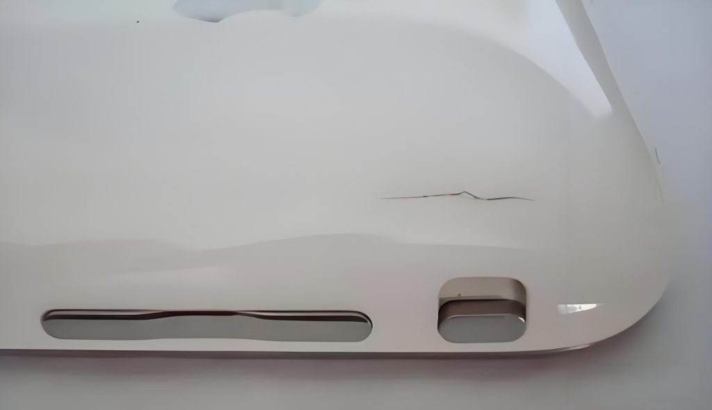
| Splay in injection molding is a surface defect appearing as silver or white streaks along the part’s flow direction. It is caused by gas — from moisture vaporising to steam, polymer degradation, shear heat, or contamination — escaping through the melt during cavity fill. The three primary root causes, in order of frequency, are moisture, heat, and shear. |
Splay is one of the most common cosmetic defects in plastic injection molding — and one of the most frustrating to diagnose because it looks the same whether the cause is wet material, a barrel that’s running too hot, an undersized gate, or a grease fitting that’s been bleeding into the cavity for three shifts. The fix for each of those is completely different.
This guide explains the four root cause categories — moisture, heat, shear, and contamination — with the specific diagnostic patterns that separate them, the parameter changes that fix each one, and the design decisions that prevent splay from forming in the first place.
What Is Splay in Injection Molding?
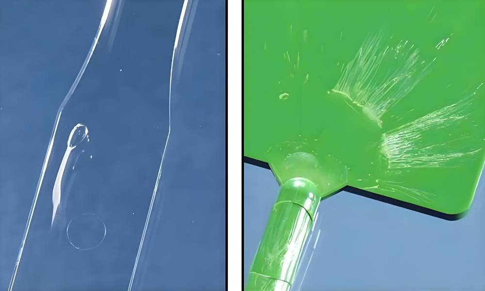
Splay (also called silver streaks, silver marks, or splash marks) is a cosmetic defect that appears on the surface of injection-molded parts as thin, shiny, silver or white streaks running in the direction of melt flow. These streaks typically impact the part’s surface finish and follow the direction of the resin flow.
Beaumont Technologies’ injection molding glossary defines splay as: ‘usually caused by a gas, usually water (steam), but can be caused by unmelt, dirt, chips, or flakes from three-plate molds, cold slugs, excessive volatile additives, air, and/or decompression’ [1].
The mechanism in every case is the same: gas forms in or enters the melt, becomes trapped, migrates to the part surface during cavity fill, and gets frozen into the surface as a streak when the skin solidifies. The gas source differs.
While splay is primarily a cosmetic problem, it can also signal a processing condition — overheating, excess moisture, shear damage to the polymer — that weakens mechanical properties even where no streak is visible.
Splay vs. Similar Defects — Don’t Misdiagnose
Splay is frequently confused with several lookalikes. Getting the diagnosis right before making process changes matters:
- Flow lines: Wavy or rippled surface marks that follow the flow front. Caused by cold material or inconsistent injection speed — not gas. Flow lines sit on the surface; splay has a slightly lifted, reflective quality
- Delamination: Flaking or peeling surface layers. Looks like splay but is caused by material incompatibility (e.g., contamination with a different polymer) or excess release agent. Delamination layers can be physically peeled; splay cannot
- Cold slugs: A solid piece of cooled material injected into the cavity, usually near the gate. Appears as a discrete blob or streak near the gate, not distributed across the part
- Burn marks: Dark or charred marks at end-of-fill locations, caused by compressed gas ignition. A different mechanism from splay, though both can coexist if venting is inadequate
Cause 1 — Moisture: The Most Common Source of Splay
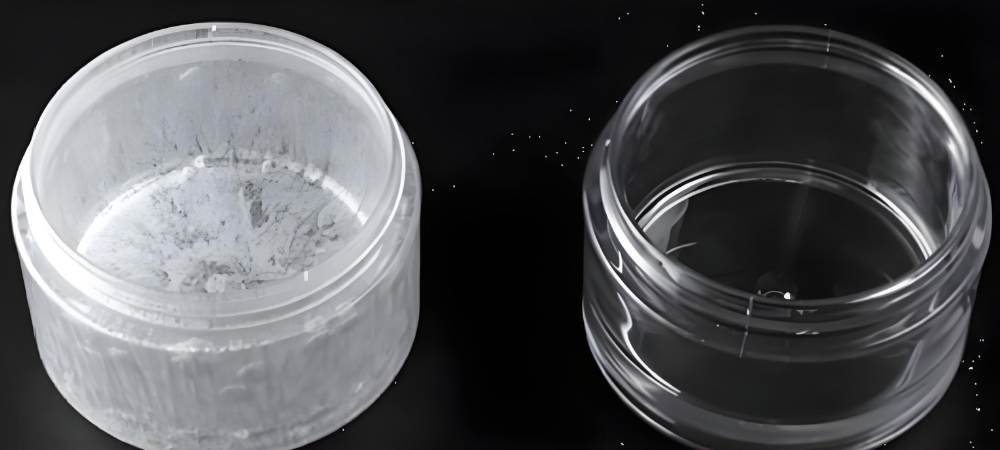
Moisture is the single most frequent cause of splay. When hygroscopic resins — nylon, polycarbonate, PET, PBT, ABS — absorb atmospheric humidity and are processed without adequate drying, the moisture vaporises to steam inside the barrel. That steam forms bubbles in the melt that migrate to the surface during fill and freeze as silver streaks.
The diagnostic tell for moisture splay is randomness across the part surface. Moisture-caused streaks don’t appear consistently in the same location from shot to shot — they are distributed wherever bubbles happen to reach the surface in that particular fill. If you’re seeing streaks that wander across the part with no fixed location, moisture is the first thing to check.
How Much Moisture Is Too Much?
Different resins have different moisture tolerance before splay appears. The table below lists typical drying requirements. Using a moisture analyser — not just touching the material to check if it’s warm — is the only reliable way to confirm a material is adequately dry [2].
| Resin | Drying Temp. | Min. Drying Time | Max. Moisture | Notes |
| ABS | 80–90 °C | 2–4 hr | ≤ 0.10% | ≤ -29°C dew point |
| PA 6 (Nylon 6) | 80 °C | 4–6 hr | ≤ 0.20% | Desiccant dryer required |
| PA 66 (Nylon 66) | 80–85 °C | 4–6 hr | ≤ 0.20% | Desiccant dryer required |
| PC (Polycarbonate) | 120 °C | 3–4 hr | ≤ 0.02% | ≤ -29°C dew point; critical — splay threshold very low |
| PET | 120–140 °C | 4–6 hr | ≤ 0.02% | ≤ -40°C dew point recommended |
| PBT | 120 °C | 3–4 hr | ≤ 0.04% | Desiccant dryer; monitor hopper throughput |
| POM (Acetal) | 80–90 °C | 2–4 hr | ≤ 0.20% | Overheating risk — bank dryer at 38°C if press idle >4 hr |
| PP / PE | 60–80 °C | 1–2 hr (if wet) | Non-hygroscopic typically | Check if stored in humid conditions; drying optional |
Note on over-drying: material that sits motionless in a hopper for extended periods can be over-dried, degrading polymer additives and causing its own form of splay. If a press will be idle for more than four hours, bank the dryer to approximately 38°C (100°F) — warm enough to maintain dryness without damaging the material [3].
Mold-Side Moisture Sources
The material isn’t always where the moisture comes from. Cooling water leaks inside the mold are a less obvious but real moisture source. Check all water fittings, particularly those mounted on top of the mold where condensation can collect.
Slides, stripper plates, and other water-cooled moving components should be inspected in their operating state, not just at rest. If chiller temperatures below 50°F (10°C) are used and the shop is humid, the mold may be sweating — condensation on the mold surface introduces moisture directly before the next shot.
Cause 2 — Heat: Overprocessing and Residence Time
Heat-related splay occurs when the polymer is exposed to temperatures above the material manufacturer’s recommended processing window for long enough that thermal degradation begins. The polymer chains break down — shorter chain fragments and gaseous volatile compounds form — and those volatiles produce streaks in the part surface.
The diagnostic pattern for heat splay: the material tests dry when checked with a moisture analyser, but splay persists. Look for stickiness or a burnt smell on the finished part — both indicate overprocessing. If either is present, barrel temperatures are the first parameter to review.
Back Pressure: The Most Overlooked Heat Cause
Excess back pressure is one of the most common and least-investigated contributors to heat splay. High back pressure forces the melt through the compression zone of the screw repeatedly, generating shear heat that builds up through the barrel.
Critical process rule: any change to back pressure requires a minimum of 20 minutes for the barrel to reach a new heat-soak equilibrium before assessing the effect on splay. Making back pressure changes and immediately evaluating the next shot produces misleading results.
Material overprocessed by excess back pressure has shorter polymer chains, which can both cause splay and reduce the mechanical strength of parts that appear visually acceptable.
Residence Time and Barrel Sizing
Splay from residence time happens when the shot size is too small relative to the barrel capacity. Material sits in the barrel too long, getting baked by the heater bands — particularly material that settles to the bottom of the barrel.
The fix is to match the machine to the shot size: the shot should be between 20–80% of the barrel capacity. If the machine is oversize for the job, splay from residence time is structurally built into the process.
When this can’t be corrected by machine selection, a screw rotation delay can help: set screw rotation to begin late, finishing recovery approximately 1.5–2 seconds before mold open. This minimizes the time the charged barrel sits idle before injection, reducing the residence-related heat soak on the last material metered in.
Cause 3 — Shear: Location-Locked Streaks
Shear splay occurs when the polymer melt experiences excessive shear rate — at the gate, in the runner, at a damaged mold feature, or from a screw running too fast — that mechanically degrades the polymer and generates gas.
The critical diagnostic distinction from moisture and heat splay is that shear splay appears consistently in the same location on every shot. If the streaks are always at the same position, shear is almost certainly the root cause.
Fill-Position Diagnostic Framework
The most powerful tool for isolating shear splay is identifying where in the fill sequence the splay appears:
- Beginning of fill: decompression suck-back pulling air into the nozzle; excessive temperature drop between nozzle and mold; gate too small for the fill speed. Reduce decompression position and speed (target: 0.1–0.4 inches of suck-back, minimum speed). Verify nozzle temperature matches mold sprue temperature within ±10°C
- Middle of fill: mold features or damaged cavity surfaces creating localised shear. Profile injection speed into six equal segments; reduce speed for the affected segment to zero, one shot at a time, to pinpoint the fill position where splay initiates. Inspect the corresponding mold area for burrs or cracks
- End of fill: gate overheating at end-of-fill or material waxing. Slow the end-of-fill injection segment; verify gate temperature; consider also speeding beginning-of-fill to get the material past the gate zone before it overheats
Gate Sizing and Nozzle Tip
An undersized gate is one of the most fixable sources of shear splay. The solution is to widen the gate, add additional gates to reduce fill velocity through each gate, or convert to a fan gate to distribute shear over a larger cross-section. Slowing injection speed at the fill segment that covers gate traverse is an immediate corrective action that can confirm whether gate shear is the cause.
Nozzle tip orifice sizing also contributes: the tip orifice should be approximately 1/16″ smaller than the sprue bushing orifice. If the nozzle tip is too small, it acts as a shear point for every shot. In a validated process where splay has newly appeared, check whether the nozzle tip has been replaced with an incorrect size.
Screw Speed
High screw RPM during recovery generates shear heat in the compression zone. Gradually reducing screw speed — giving 20 minutes between adjustments for the barrel to heat-soak at the new condition — will reveal whether screw shear is contributing. The effect of screw speed changes takes time to propagate through the barrel; immediate evaluation produces noise, not signal.
Cause 4 — Contamination: The Easy-to-Miss Fourth Cause
Contamination is the fourth root cause and is addressed last in the diagnostic sequence — after moisture, heat, and shear have been excluded. Contamination-related splay arises from foreign material in the melt stream: excess mold lubricant, degraded regrind, residual material from a previous run, or particulate from worn equipment.
The pattern: splay that appears immediately after the mold has returned from the toolroom is lubricant contamination until proven otherwise. Oil from ejector pins, lifters, or slides bleeds onto the cavity surface when applied in excess and creates streaks on the first few shots.
The fix is to wipe the cavity, purge 2–3 shots to clear the nozzle and runner, and use only the minimum amount of lubricant — or switch to a dry-film lubricant that leaves no residue.
Material changeover contamination: when changing resins, purge the barrel completely. Drain 20–25 lbs from the feed throat before beginning the new run — material sitting in the feed throat between the dryer and machine has been in contact with the previous material’s residue and can cause streaks in the first shots of the new material.
Splay Diagnostic Table: Pattern → Root Cause → First Fix
Use this table as the first step in any splay troubleshooting sequence. Identify the pattern, confirm the category, then apply the targeted fix before making broader process changes.
| Splay Pattern Observed | Most Likely Root Cause | First Corrective Action | Category |
| Random, all over the part — never same location | Moisture in resin | Dry material per spec; inspect mold for water leaks | Moisture — most common |
| Consistent same location every shot | Shear at gate or mold feature | Slow injection at that fill segment; inspect gate for burrs | Shear — location-locked |
| Splay after long idle or shift start | Heat / excess residence | Reduce feed-zone temp; add screw rotation delay | Heat — residence time |
| Appears after barrel zone heater fault or spike | Heat — barrel overtemp | Verify actuals vs. setpoints; check thermocouple seating | Heat — equipment fault |
| Splay starts at beginning of fill only | Shear — decompression / cold slug | Reduce decompression position/speed (0.1–0.4″); check nozzle temp | Shear — start of fill |
| Splay at middle of fill | Shear — mold feature / burr | Profile injection speed; inspect mold cavity for damage | Shear — mid-fill |
| Splay at end of fill | Shear — gate overheating at end | Slow end-of-fill segment; verify gate temperature | Shear — end of fill |
| Splay after mold returned from toolroom | Contamination — excess lubricant | Wipe cavity; purge 2–3 shots; inspect ejector pins for grease bleed | Contamination — mold |
| Splay after material changeover | Contamination — residual material | Purge barrel fully; drain 20–25 lbs from feed throat | Contamination — barrel |
| Irregular, flake-like, not streak-shaped | Delamination (NOT splay) | Investigate material compatibility; check for regrind contamination | Not splay — different defect |
Preventing Splay: Design and Process Best Practices
Resolving splay injection molding flaws is crucial for ensuring quality control and achieving cost-effectiveness. Every broken component necessitates additional scrap or rework. Both increase production cost and waste valuable resources. A proactive strategy is required to stop splay.
Material Handling and Storage
- Store hygroscopic resins in sealed containers with desiccant. Once opened, use within the manufacturer’s recommended time window
- Use a desiccant (molecular sieve) dryer — not a simple hot-air dryer — for PC, nylon, PET, and PBT. Hot-air dryers cannot achieve the dew point required for these materials
- Test moisture content with a moisture analyser before production startup. A warm bag of material is not a dried bag of material
- At startup, drain 20–25 lbs from the feed throat to remove material that has absorbed moisture during idle time
Process Parameter Management
- Set barrel temperatures at the low end of the material’s processing window and increase only if needed — it is easier to add heat than to remove the damage caused by excess heat
- After any back pressure change, wait 20 minutes before evaluating the effect. The barrel needs a full heat-soak cycle to reach equilibrium at the new condition
- Match machine barrel size to shot size: the shot should use 20–80% of barrel capacity. Oversized machines with small shots create residence-time splay by design
- Set decompression (suck-back) to the minimum position needed — target 0.1–0.4″ at minimum speed. Excessive decompression pulls air into the nozzle tip, causing beginning-of-fill splay on every shot
- Set screw rotation delay so recovery finishes 1.5–2 seconds before mold open. This minimises barrel idle time and reduces heat accumulation in the last-in material
Mold Design for Splay Prevention
- Size gates adequately for the fill velocity — undersized gates are a primary and tooling-correctable source of shear splay
- Include a cold slug well at the end of the main runner to capture cooled nozzle material before it enters the cavity
- Verify and maintain mold venting: clogged parting-line vents trap gas and cause splay at end-of-fill locations. Clean vents every 4 hours on sensitive materials
- Ensure cooling channels are leak-free. A water leak inside the mold introduces moisture into every shot as long as it runs
- Size the nozzle tip orifice 1/16″ smaller than the sprue bushing orifice to prevent localised shear at the nozzle-sprue interface
Frequently Asked Questions
How do I identify whether splay is caused by moisture, heat, or shear?
The location pattern is the primary diagnostic: moisture splay is random across the part with no consistent location shot to shot; heat splay persists even when material tests dry, often with a burnt smell or sticky surface; shear splay appears consistently in the same location on every shot.
What causes splay that appears immediately after a mold returns from the toolroom?
Contamination from excess lubricant applied during maintenance. Oil from ejector pins, lifters, or slides bleeds onto the cavity surface and produces splay on the first several shots. Wipe the cavity, purge 2–3 shots, and reduce lubricant volume. If recurring, switch to a dry-film lubricant that leaves no residue.
What is the minimum moisture content that causes splay?
It depends on the resin. Polycarbonate begins showing splay at moisture contents above 0.02% — one of the lowest thresholds of any engineering resin, which is why PC requires a dedicated desiccant dryer at 120°C.
Nylon (PA6/PA66) tolerates up to 0.20%. ABS is typically specified at ≤0.10%. Using a gravimetric moisture analyser is the only reliable method — touch and temperature checks are not sufficient for sensitive materials.
Can splay be fixed without tooling changes?
In the majority of cases, yes — moisture, heat, and many shear causes are process-correctable without touching the mold. The exceptions are gate-size-induced shear (requires gate modification) and vent blockage (requires vent cleaning).
Conclusion
Splay is solvable. The reason it persists on so many production floors is that teams make process changes — temperature, speed, pressure — based on guesses about the root cause rather than on a systematic reading of the defect pattern.
The fill-position diagnostic framework (random vs. location-locked, beginning vs. middle vs. end of fill) and the four-cause structure (moisture, heat, shear, contamination) give you the logic to isolate the root cause before making a single process change.
Fecision’s injection molding services supports customers through DFM, tooling, and process development. For consultation on recurring splay defects or gate design reviews, see more and contact our engineering team.
References & Citations
All sources publicly available. No competitor backlinks. Accessed April 2026.
[1] Beaumont Technologies, Inc. ‘Splay — Injection Molding Glossary.’ Beaumont Technologies. https://www.beaumontinc.com/injection-molding-glossary/splay/
[2] PlasticsToday / Garrett MacKenzie. ‘The Troubleshooter: The Role of Moisture in Injection Molding Splay Defects.’ https://www.plasticstoday.com/injection-molding/the-troubleshooter-the-role-of-moisture-in-injection-molding-splay-defects
[3] Plastic411 / MacKenzie. ‘Splay Defects in Plastic Injection — Moisture, Heat, Shear Analysis.’ Plastic411.com. https://plastic411.com/splay-defects-in-plastic-injection/
[4] Chem-Pak. ‘Injection Mold Flaws & How to Prevent Them: Contamination, Splay, & Delamination.’ Chem-Pak.com. https://chem-pak.com/preventing-contamination-splay-delamination/


