
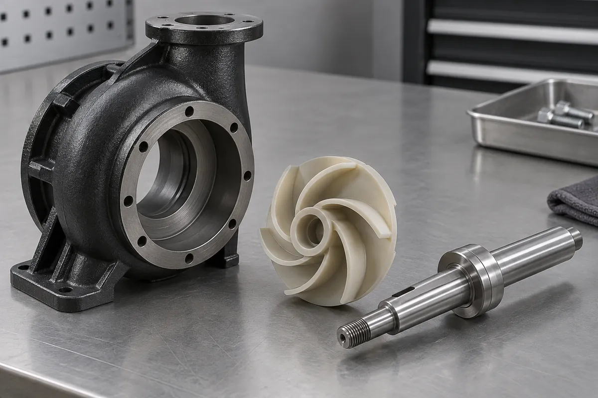
Product design illustrations. Final geometry, materials and acceptance criteria are project-specific.
A molded impeller is not a complete pump, and a dimensionally acceptable impeller does not establish a pump performance curve. The housing, shaft, clearances, motor, fluid and operating point all contribute to the system result. Validation should connect the component inspection to a clearly identified assembled configuration.
Begin with the intended duty and the questions the test must answer. Flow, head, power, leakage, vibration and endurance are different measurements. Choose the relevant outcomes and acceptance boundaries before arranging a demonstration that produces an impressive but poorly defined number.
Freeze the configuration being evaluated
Record the impeller revision, material and manufacturing state, including any welding, bore finishing or balance correction. Identify the housing, shaft and other mating components. Without this information, a later production assembly may differ from the tested one while still being described by the same product name.
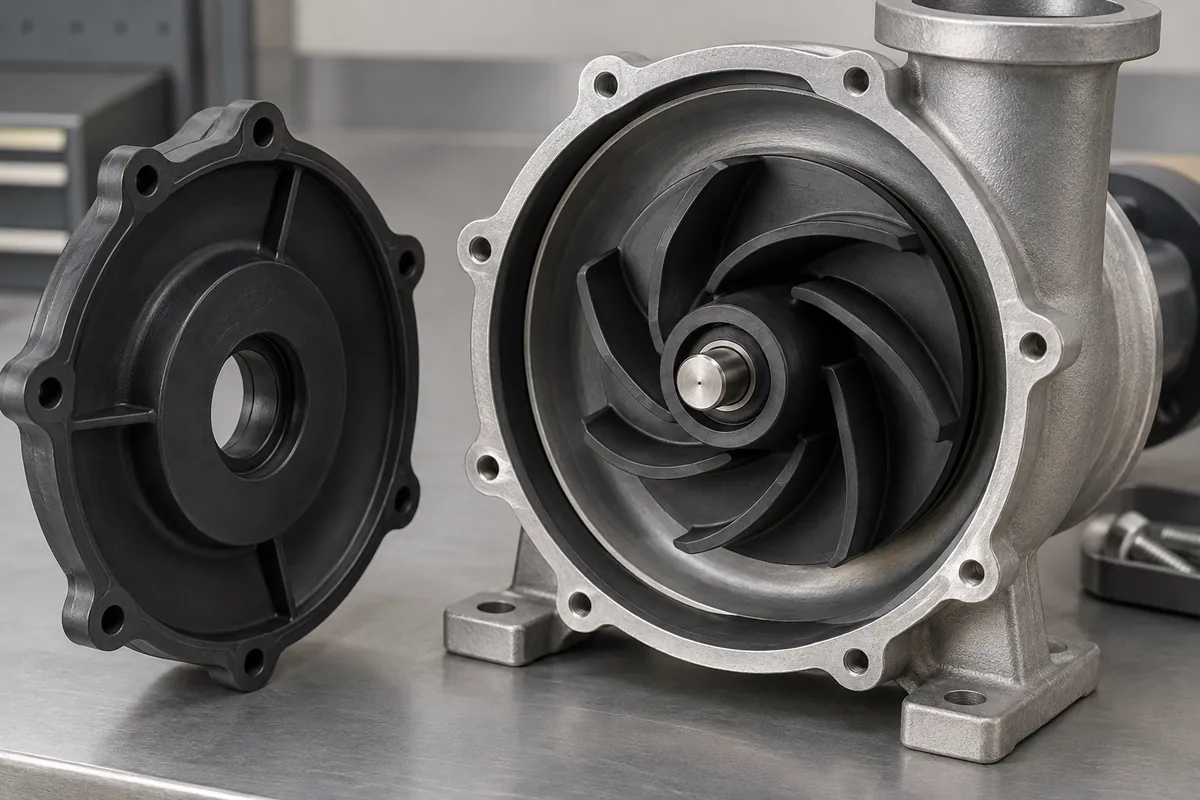
Confirm installation and clearances using the agreed method. A component forced into position or adjusted during a test can produce a result that is difficult to reproduce. Any shims, assembly aids or special adjustments should be recorded rather than disappearing into an informal setup procedure.
Keep component reports available separately. Bore dimensions, runout and balance help establish the starting condition, but they do not replace system measurements. Conversely, one successful pump test should not be used to waive a specified component requirement without an explicit engineering decision.
Describe the operating point and measurement method
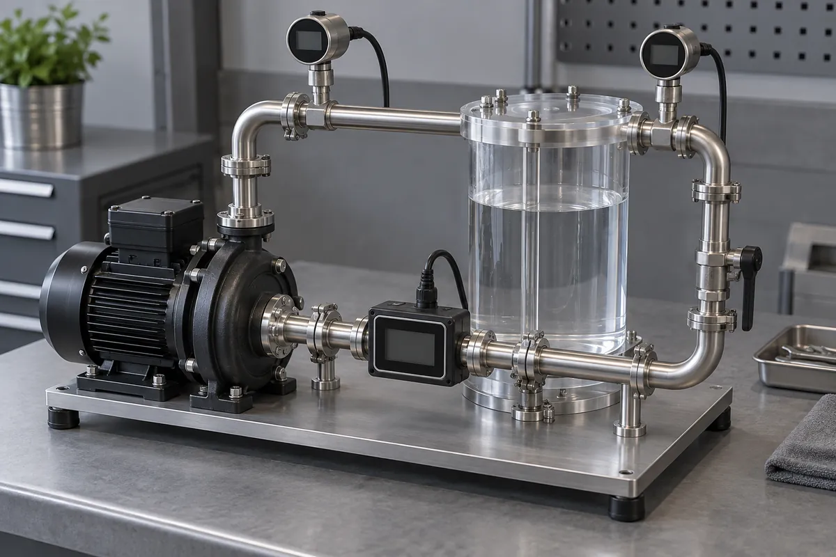
State speed, fluid identity and temperature, together with the relevant inlet and outlet conditions. A flow reading without the associated pressure or head condition cannot describe the complete duty. Different test restrictions can produce different results from the same assembly.
Use calibrated instruments and identify where measurements are taken. Pressure losses between the pump and a remote measurement point can affect interpretation. The test team should define the method so a repeated test or a supplier comparison uses equivalent conditions.
The KSB pump reference is useful background for system terminology. Project acceptance should still use an agreed procedure and the applicable requirements rather than an isolated generic statement about impeller performance.
Separate performance mapping from endurance
A short performance run can show behavior at selected conditions, but it does not establish durability. If endurance matters, define the duration, cycling, temperature and stop criteria separately. Include inspections that can reveal progressive damage or drift before the component stops functioning completely.
Do not accelerate a test by raising speed or temperature without assessing how that changes the failure mechanism. A more severe condition is not automatically a valid substitute for the intended duty. State the reasoning and limitations of any accelerated evaluation in the report.
Track sample population and coverage. One development assembly may support a design decision, while production release may require a broader plan across cavities or lots. Report the actual number tested and avoid turning a selected demonstration into a population-wide reliability claim.
Establish how the system will be returned to the same condition between tests. Residual fluid, temperature drift or a changed valve setting can make consecutive runs differ without a component change. Recording stabilization and reset conditions improves the value of a comparison between two impeller revisions and reduces unnecessary tooling changes.
Use results to close specific requirements
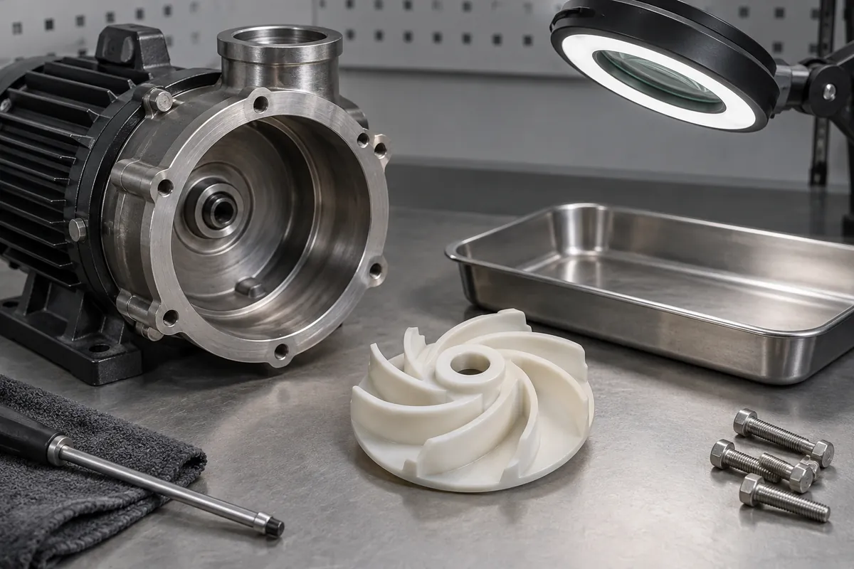
When a result falls outside the requirement, investigate the whole configuration. A problem may originate in the component, assembly, fixture or operating setup. Preserve the data and identify what changed before rerunning the test, so the new result can be compared meaningfully with the original one.
Link findings back to material selection and rotating-component checks. These reviews support each other but should not be collapsed into one pass statement that conceals untested conditions.
The final release should identify completed requirements, remaining validation and the configuration to which each conclusion applies. This gives purchasing a precise supply specification and gives future engineering changes a trustworthy baseline instead of a collection of unrelated favorable test numbers.
Discuss the component and its acceptance requirements
Explore our custom plastic impellers and the related project case study. Send the current drawing, mating-part details, operating conditions and required quantities. We can review tooling, molding and inspection as a defined supply scope, with development samples and production approval kept separate.