
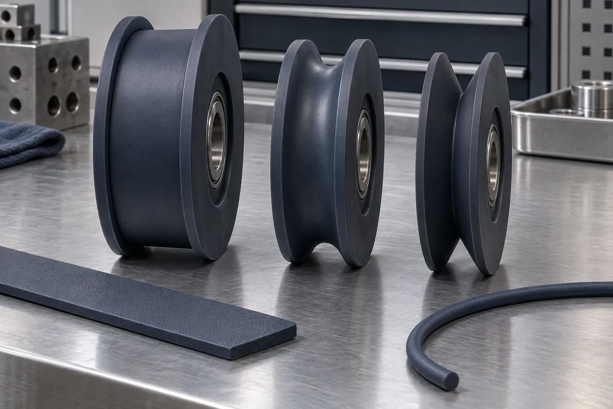
Product design illustrations. Final geometry, materials and acceptance criteria are project-specific.
The groove in a plastic pulley is an interface, not a decorative feature. Its shape determines where a belt or cord contacts the wheel and how that contact changes with alignment and loading. Choosing a groove by appearance or outside diameter can produce a part that fits into the machine but interacts poorly with the moving component.
Begin by naming the mating element and its intended function. A round cord, a V-belt, a flat belt and a synchronous belt require different discussions. A smooth idler contacting the back of a belt is also different from a drive pulley engaging its working face. Similar-looking wheels are not automatically interchangeable between these roles.
Use the mating specification as the starting point
Request the belt or cord designation and relevant supplier guidance, including permitted pulley arrangements. The Gates preventive-maintenance manual separates belt sections, pulley grooves and idler considerations. That separation is important: a dimension from one belt family should not be copied into an unrelated custom wheel simply because both parts have grooves.
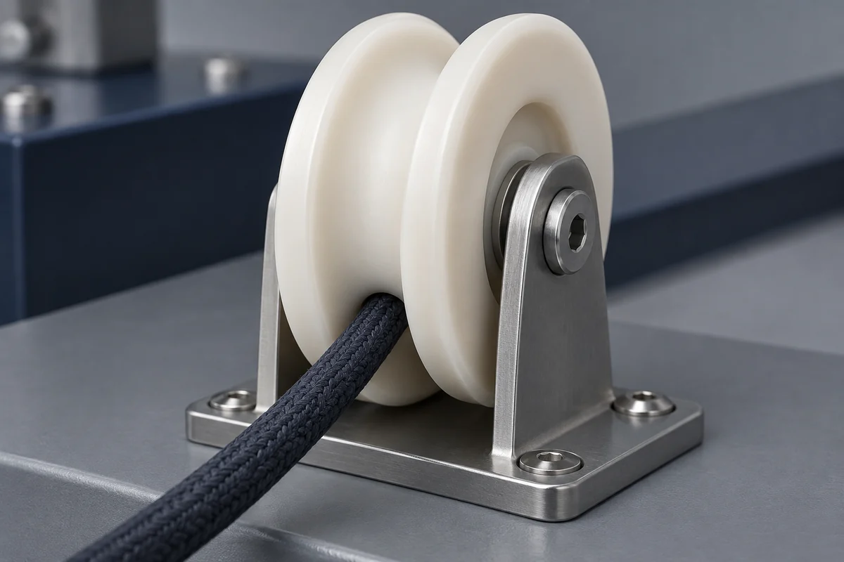
For a round cord, review the groove radius, opening and contact location with the actual cord size and deformation. Avoid assuming that squeezing the cord more tightly always improves guidance. For a V-belt, the specified section and sidewall relationship matter. For a toothed belt, pitch and tooth profile need the appropriate system definition rather than an approximate molded pattern.
Define width, clearance and alignment together
Show the available lateral space and any flanges in the assembly drawing. Flanges may limit movement, but persistent rubbing can indicate an alignment or tracking issue that the flange alone cannot solve. Include the relative position of neighboring pulleys and the expected range of the mounting arrangement, not just an isolated section of the wheel.
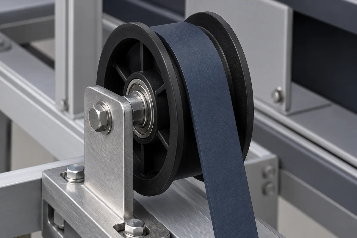
A wide flat tread may be suitable for one guiding arrangement while a narrow constrained channel serves another. Explain whether edge contact is intended or should be avoided. That information determines which surfaces need tighter control and where witness marks may be acceptable. A generic instruction for a smooth finish does not communicate these functional priorities.
Consider the full movement range. A belt that appears centered at rest may shift under the actual load or during a change in direction. The designer should identify the relevant operating states and acceptance conditions. The molding supplier can review manufacturability, but cannot infer a validated tracking system from a static wheel model alone.
Connect the profile to the molded construction
Review where the parting line, gate witness and ejection features fall relative to the contact track. A convenient tool split may leave a discontinuity where a sensitive belt runs. Discuss the permissible surface condition and whether a different tool arrangement or finishing operation is necessary. Do not promise a completely mark-free molded surface without a defined visual or functional standard.
Flanges, hubs and reinforcing ribs affect cooling and the resulting geometry. A locally thick hub connected to a thin tread deserves a molding review rather than an arbitrary global shrink allowance. Ask how the selected compound and process will be evaluated on the actual profile. A material change may require that discussion to be reopened.
Inspect the feature that controls contact
An outside-diameter measurement alone may miss a groove-profile error. Identify the section or surfaces that establish the fit and specify how they will be checked. Optical comparison, suitable gauges and dimensional measurements answer different questions. The method must be capable of resolving the relevant geometry without distorting a thin polymer feature.
Also connect the profile to the bearing or bore axis. A correct section that runs unevenly can change the contact during rotation. Our runout inspection guide describes how to separate size, radial movement and side-face movement. Keep those results distinct so a corrective action addresses the actual defect.
If a supplier proposes a geometry adjustment for mold release or tool access, identify the changed contact condition explicitly. A small angle change can be insignificant on a nonfunctional wall but important on a belt-contact flank. Review such changes with the application designer instead of treating all draft additions as automatically acceptable.
Validate the profile in its assembly
Use the controlled belt or cord, mounting arrangement and relevant load conditions for functional evaluation. Record tracking, contact marks and any debris alongside the dimensional report. A prototype that rotates freely without its mating element does not establish that the groove is appropriate. The wear-test plan can help define a more informative comparison.
Keep the approved wheel drawing and mating specification linked in the release record. If the belt supplier, section, material or mounting changes later, review the interface again. The goal is a repeatable contact design for a defined application, not a supposedly universal groove that can be substituted into any machine using the same overall pulley size.
Discuss a defined pulley application
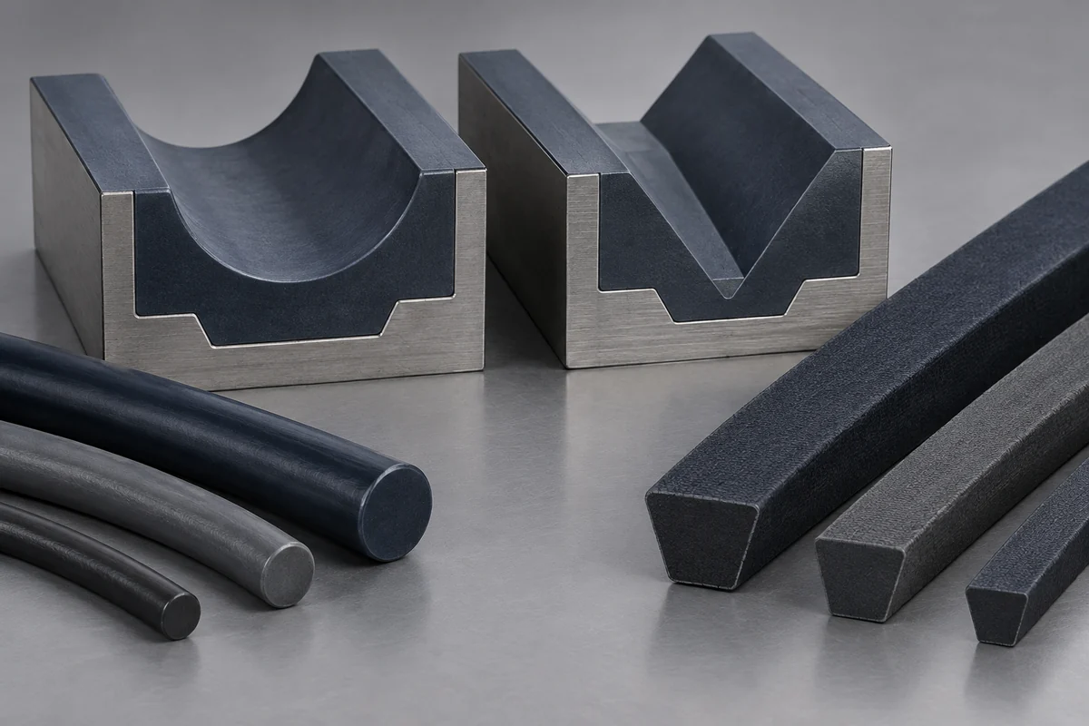
Explore our custom injection-molded plastic pulleys. Send the component drawing, mating belt or track, bearing specification and acceptance requirements to review tooling, molding and inspection as one supply scope.