
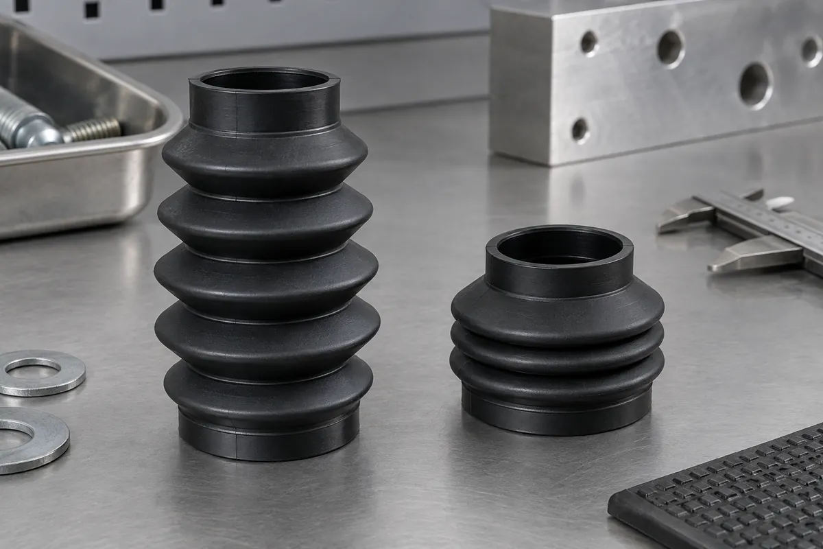
Product design illustrations. Final geometry, materials and acceptance criteria are project-specific.
The length of a bellows at rest does not define its usable stroke. The folds need space to close and room to extend without an unintended local strain or collision. End attachments also constrain the moving shape, so the functional envelope belongs to the installed assembly rather than the loose part alone.
Specify three positions clearly: free length, minimum installed length and maximum installed length. State whether a quoted stroke is total travel or displacement from a reference position. A drawing that says forty millimeters of stroke without this distinction can lead two suppliers to evaluate different motion requirements.
Understand what the convolutions must accommodate
During compression, neighboring folds approach one another and may contact. The number of folds, their profile and local wall thickness influence how the available space is used. Adding more convolutions does not automatically improve the design if the compressed package or tool-release route becomes impractical.
During extension, the folds open and the local shape changes. Review the transition into the end collars as well as the repeated central profile. A stiff attachment region can concentrate movement nearby, so a symmetric-looking free part may deform unevenly once its ends are installed.
Check the inside envelope around the protected mechanism. A bellows that clears a shaft at rest may contact it when compressed or displaced sideways. The full moving geometry should be assessed, including any fasteners, joints or shoulders inside the protected volume.
Review stroke with the actual attachments
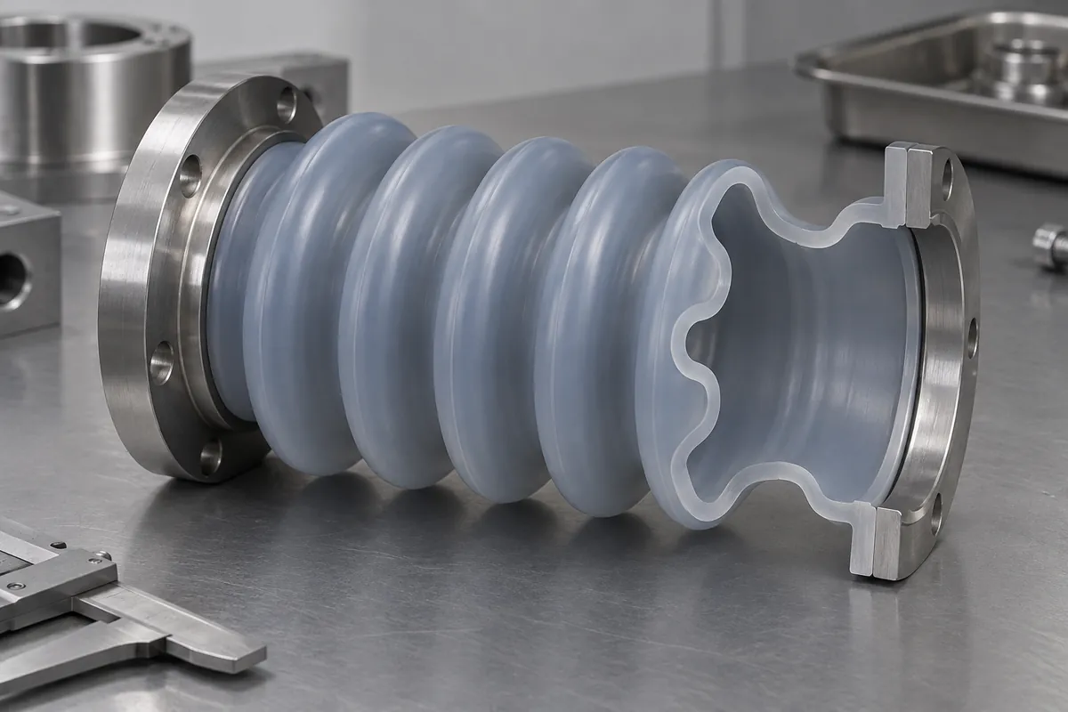
Clamps, flanges and collars can reduce the flexible length available for movement. Include them in the section model rather than measuring stroke from the outermost ends of an unmounted part. The assembly drawing should identify which regions are constrained and which are intended to flex.
Account for alignment and any lateral movement. A mechanism described as axial may still produce offset through installation tolerance or bearing clearance. Decide what combination of motion the bellows must accommodate instead of approving axial travel and assuming every other displacement is negligible.
Specialist protective-cover systems are designed around the mechanism they protect. The same application-first approach is useful for a molded silicone boot, without transferring another cover's load or durability rating to it.
Separate movement from endurance
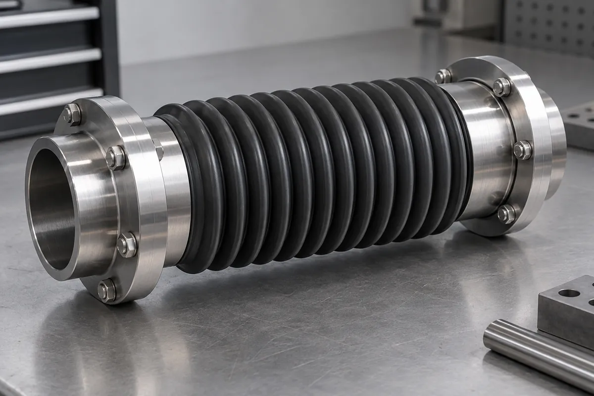
A manual check that the part reaches both positions confirms a limited geometric observation. It does not establish repeated-cycle life, sealing or resistance to a particular environment. Keep this early check useful by stating its purpose and avoiding a broader qualification claim.
Record force where it affects the mechanism. Bellows resistance can change with position and with trapped air if the volume is sealed. A motor or actuator should not be selected on the assumption that a soft-looking cover adds negligible load throughout its travel.
Review material and wall distribution with the molding supplier. A nominal hardness is not a direct measure of installed spring behavior. A change in compound or thickness can alter movement, assembly and demolding, so these decisions should be evaluated together rather than sequentially.
Compare the required motion with the surrounding equipment envelope, including service access. A boot that meets its stroke limits can still obstruct a nearby sensor or fastener when its folds expand outward. Checking these neighboring components at the travel extremes prevents a successful bench movement from becoming an installation interference.
Define the acceptance envelope
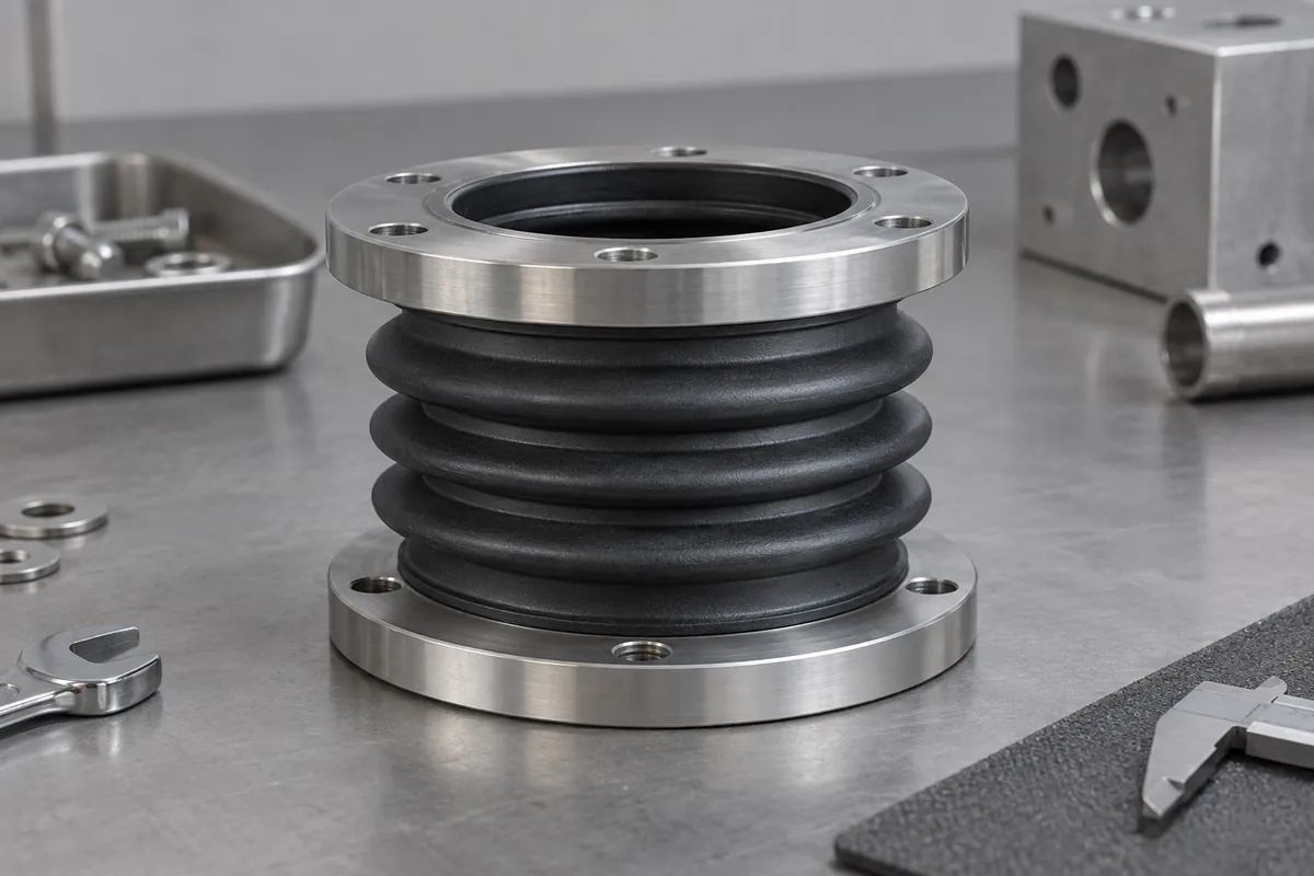
Test representative molded samples in fixtures that reproduce the real end attachments. Observe contact, twisting, recovery and any local damage through the intended motion. Record the configuration so a later tool revision can be compared under the same conditions.
Follow with an appropriate fatigue program where repeated movement is required. Keep the completed cycle count, target and sample population separate. Reaching the nominal compressed length once cannot justify a lifetime statement.
Include motion limits in the product release rather than leaving them only in a development email. If the mechanism later gains travel, changes its attachment spacing or introduces offset, the bellows requirement has changed even if its part number and free dimensions remain the same.
Discuss the component and its acceptance requirements
Explore our custom silicone bellows & boots and the related project case study. Send the current drawing, mating-part details, operating conditions and required quantities. We can review tooling, molding and inspection as a defined supply scope, with development samples and production approval kept separate.