
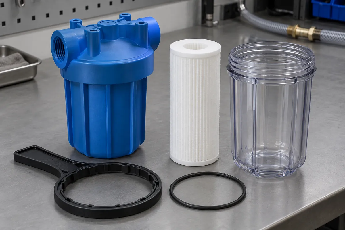
Product design illustrations. Final geometry, materials and acceptance criteria are project-specific.
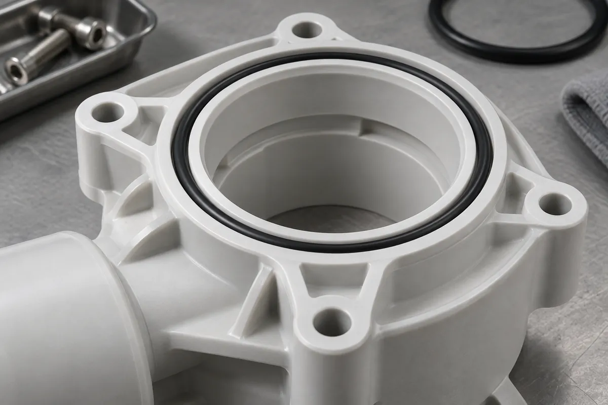
An O-ring groove is a functional interface, not a recess added after the housing design is complete. Its geometry must match the selected seal, mating surfaces and operating conditions. A groove that looks reasonable in CAD can still produce insufficient contact, installation damage or excessive confinement in the assembled housing.
Identify the sealing arrangement first. A face seal and a radial seal use the available space differently, and pressure direction can affect the relevant geometry. Record the seal size and compound together with the housing and counterpart revisions before selecting groove dimensions.
Design the gland as a complete volume
The seal needs controlled deformation and room for the relevant dimensional and environmental changes. Groove width, depth and surrounding clearances interact, so changing only one dimension can create a new issue. Do not use a single universal squeeze percentage without considering the seal type and application.
The Parker O-Ring Handbook discusses gland design, installation and extrusion considerations. Use the applicable guidance with the actual pressure, temperature, compound and tolerance conditions rather than copying an unrelated drawing example.
Include the mating component in the tolerance review. The assembled gap may depend on several dimensions and on how the closure seats. Inspecting the groove alone cannot prove that the final seal experiences the intended condition at all allowed tolerance combinations.
Protect the contact surfaces
Gate remnants, flash, parting-line mismatch or scratches can matter where they cross the sealing path. Mark the critical contact zones on the drawing and review how the tool and finishing process will keep them within the agreed condition. A general cosmetic note may be too vague for this purpose.
Provide an installation path that does not force the seal across an uncontrolled sharp edge. The entry geometry, assembly direction and any approved lubricant belong in the review. A seal damaged during installation may produce intermittent leakage that looks like a molding variation until the assembly is examined.
Review whether the seal can twist or leave its groove as the closure is installed. The risk depends on the geometry and assembly action. A development check should observe the practical installation sequence rather than assume the seal remains exactly where the section drawing places it.
Measure with a repeatable reference
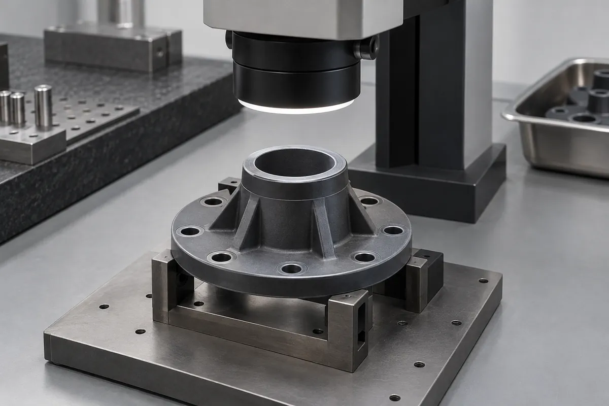
Choose references that reproduce the seating relationship between the housing and its counterpart. Groove depth measured from an unrelated surface may not control the assembled gap. State which face is the functional reference and how the part is supported during inspection.
For a circular groove, consider variation around the perimeter rather than relying on one local reading. Warpage or local molding variation can change the sealing condition even when an average dimension is acceptable. Agree the sampling locations and report the observed range where it matters.
Link cavity and lot identity to the inspection results. If leakage appears only in one cavity or after a particular assembly operation, that information can narrow the investigation. Combining all results into one average can conceal the pattern that would explain the failure.
When a groove dimension is revised, review the available seal variation again rather than checking only the new nominal section. A change that improves one tolerance combination can worsen another. The drawing should preserve the agreed relationship between housing, counterpart and seal across the permitted production range, not only at nominal size.
Validate after the relevant exposure
Test with the actual seal compound and assembly method. Temperature, fluid exposure and time under compression can affect the interface, so an initial room-temperature check may not cover the intended duty. Define conditioning and repeated opening where the housing is serviceable.
Use the specified leak-test method and record the assembly configuration. When a failure occurs, distinguish the O-ring interface from port leakage or a fixture leak before revising the groove geometry.
Keep the approved seal, groove, counterpart and installation method together in the release record. A later change of seal supplier, compound or cross-section should prompt a compatibility and fit review rather than being treated as an interchangeable purchasing substitution.
Discuss the component and its acceptance requirements
Explore our custom plastic filter housings and the related project case study. Send the current drawing, mating-part details, operating conditions and required quantities. We can review tooling, molding and inspection as a defined supply scope, with development samples and production approval kept separate.