
Custom molded parts · Made to your design
Custom Molded Connector Insulators and Terminal Carriers
Keep the terminal interface, molding plan and inspection reference in one controlled design review.
Bring us your insulating-body or terminal-carrier drawings for a project-specific molding quotation. We review the plastic geometry with its mating components, material requirements and approval evidence—not as a generic complete-connector supply package.
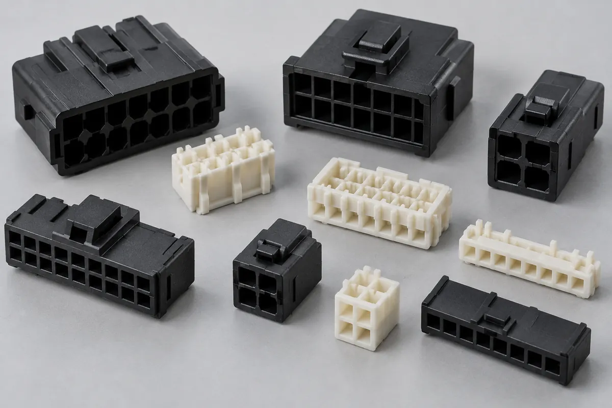
Product details
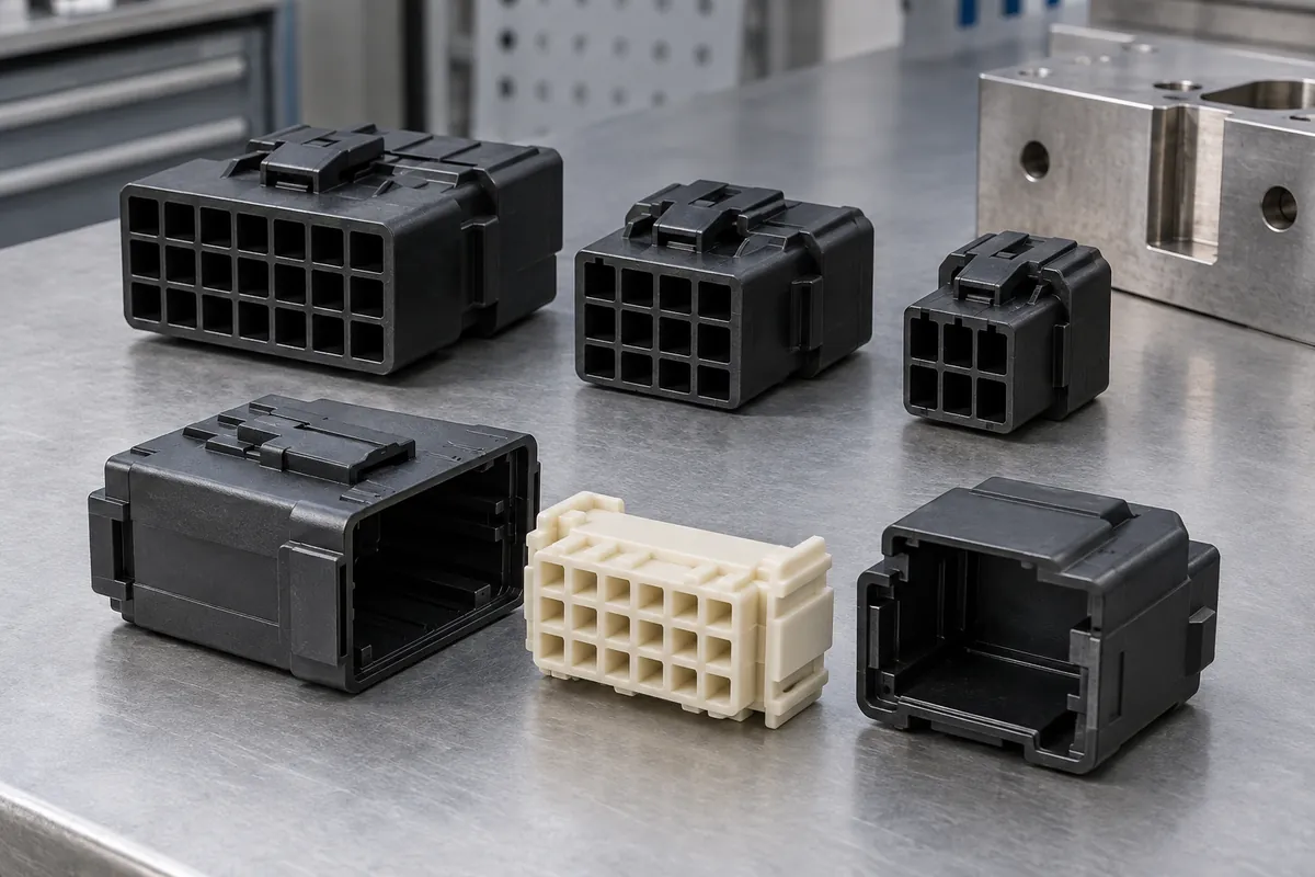
Terminal windows, locating faces and assembly interfaces
Explore design examples of the plastic features that guide, locate and support an electrical connector assembly.
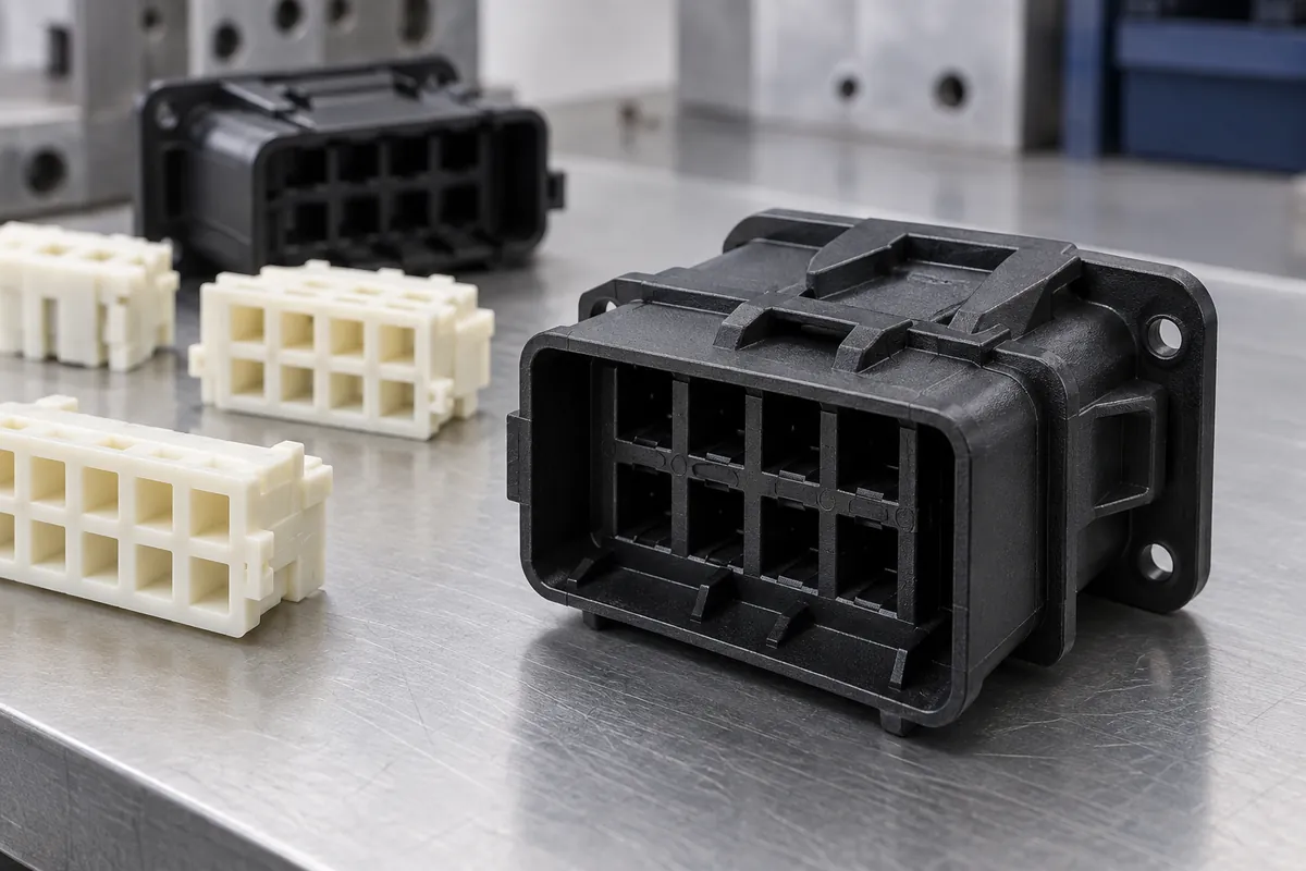
Insulating body
Review the insulating envelope and the features that must remain fixed for the mating assembly.
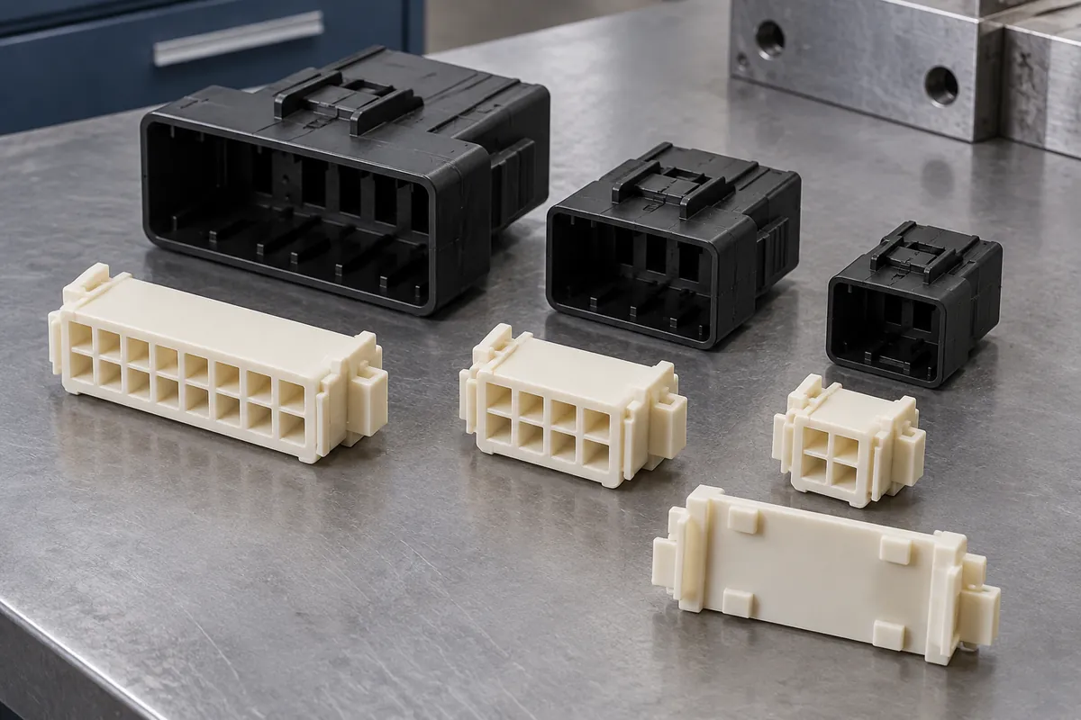
Mounting references
Identify the mounting and locating features used by both assembly and inspection.
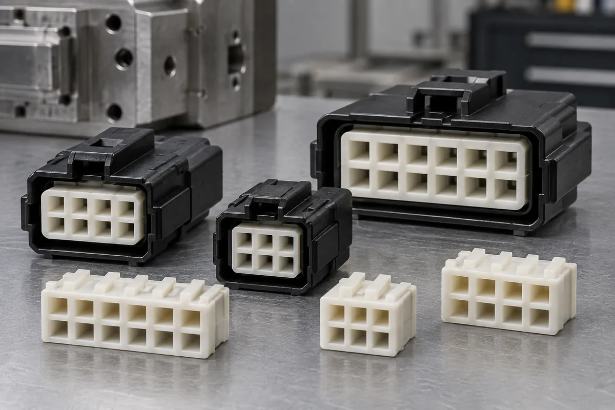
Terminal-window array
Define aperture geometry, local spacing and pattern location as distinct requirements.
Assembly relationship
Share counterpart revisions even when contacts or the completed assembly are outside the molding scope.
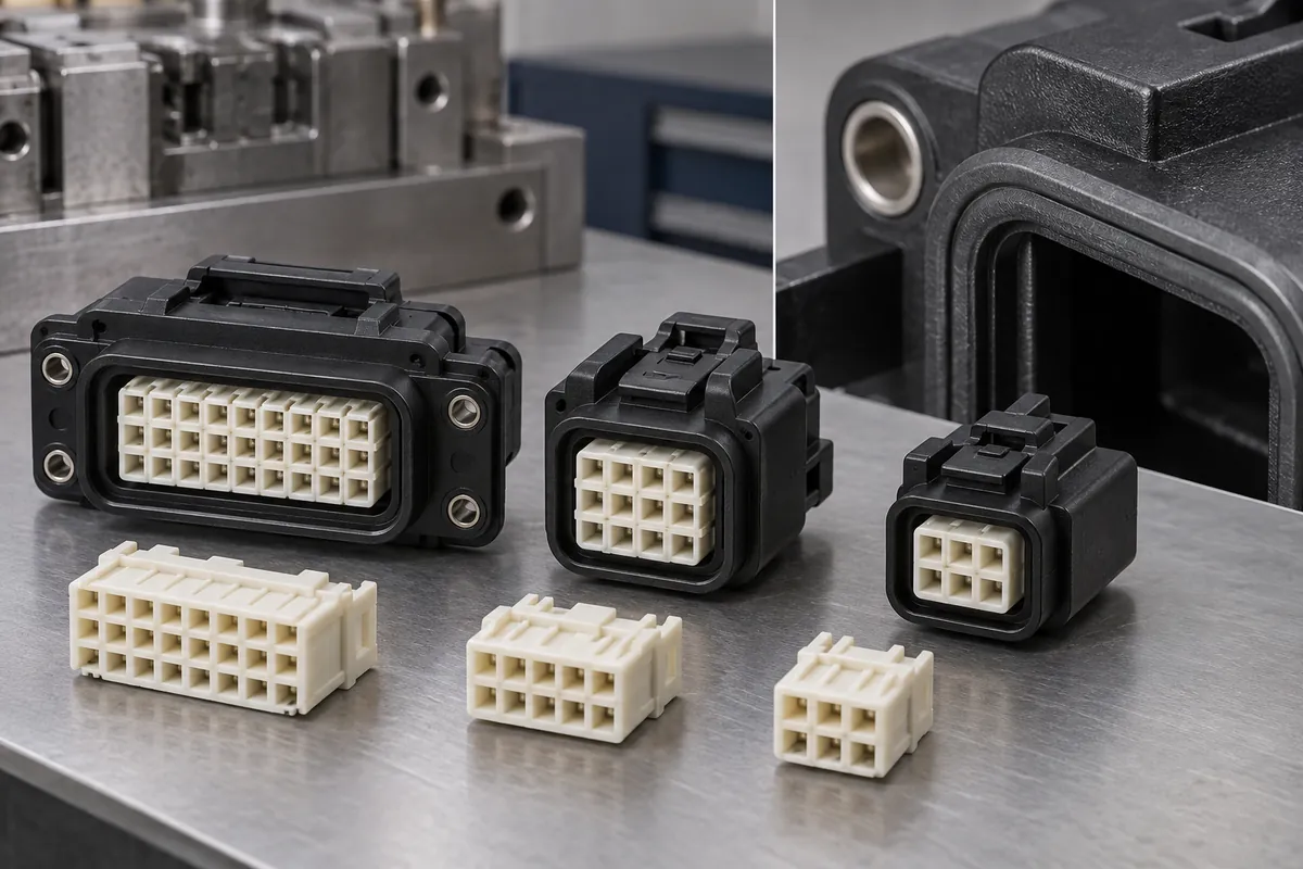
Seal-interface detail
Specify the plastic interface; assembled sealing performance needs its own agreed qualification.
Illustrative configurations. Final specifications follow your approved drawings.
Application fit
Plastic component supply with a clear boundary
The part may guide contacts, locate an assembly or provide a sealing interface. Each function needs defined geometry and evidence. No electrical rating or finished-connector certification is assigned to these design examples.
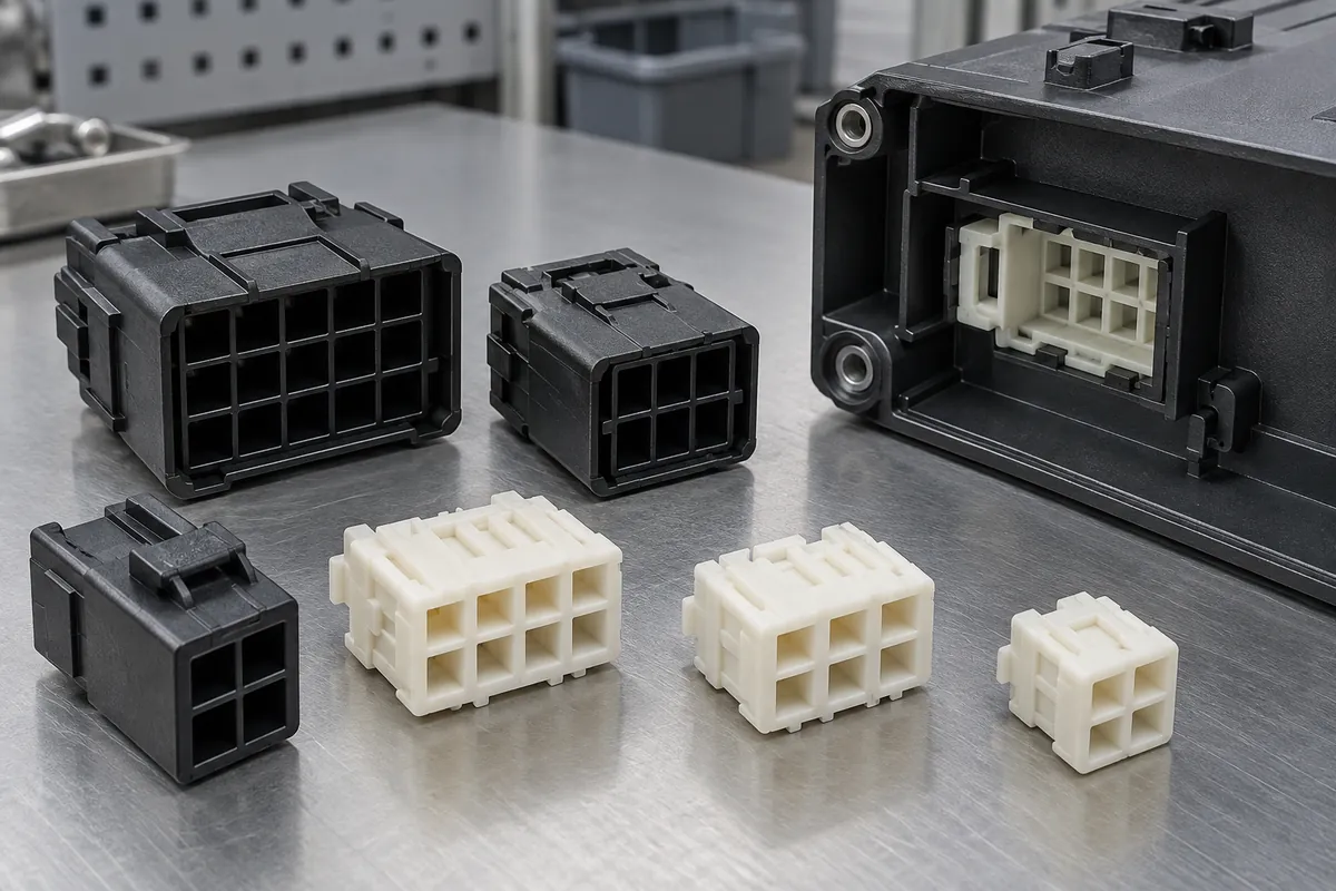
Connector insulating bodies
Empty shells and housings for customer-defined terminal arrangements. Review terminal entry, retention features, wall geometry and permitted manufacturing changes.
Terminal carriers
Molded carriers that establish a specified contact pattern. Include the terminal installation sequence and the reference features used to locate the carrier.
Interface and locating parts
Plastic separators, locating pieces and connector-adjacent components where the drawing clearly defines the delivered item and its assembly responsibility.
Quote-ready inputs
What to send for a meaningful quotation
Use the same drawing and requirements for every proposal. Mark open decisions explicitly so that a low price does not conceal a different deliverable.
| Area | Please provide | Review before release |
|---|---|---|
| Geometry | CAD, drawing revision, terminal and counterpart details. | Critical interfaces, no-change features, gate and parting-line restrictions. |
| Material | Exact grade if selected, color, reinforcement and documentation needs. | Grade-specific filling, exposure and application requirements. |
| Assembly | Terminal installation, locating scheme, mating action and supports. | Define the plastic component check separately from complete-assembly tests. |
| Thermal exposure | Actual process profile, part state and required post-exposure function. | No generic reflow-temperature guarantee from a resin-family name. |
| Inspection | Datums, feature list, gauges, sample state and report format. | Local pitch, overall pattern location and cavity-level evidence. |
| Supply | Trial quantity, first order, repeat demand, packing and delivery. | Tooling scope, approval hold points and traceability requirements. |
From drawing to approval
Approve the configuration, then release production
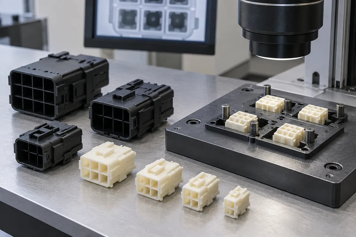
Align the documents
Reconcile CAD, drawing, terminal and counterpart revisions. Mark unresolved interfaces and the person responsible for each decision.
Review resin and tooling
Confirm the candidate grade and review filling, critical surfaces, mold release and any proposed drawing changes.
Evaluate identified samples
Link dimensional and functional results to sample and cavity IDs. Keep thermal or assembled-product testing separately identified.
Control the release
Record the approved configuration, evidence, remaining exclusions and changes that would require a new review.
Practical engineering and buying guides
Six decisions to make before production
- Molded Connector Insulators: An RFQ Checklist for BuyersPrepare a connector-insulator RFQ with mating geometry, resin, terminal assembly, inspection, traceability and clear production approval boundaries.
- Connector Pin Pitch and Datum Inspection for Molded PartsSeparate aperture pitch, total span and datum-based position when inspecting molded connector carriers. Define support, conditioning and feature-level records.
- Reflow Exposure Requirements for Molded Connector PartsSpecify reflow exposure for molded connector parts using the actual thermal profile, resin grade, sample condition and post-process inspection requirements.
- Connector Approval: Functional Gauges vs Individual DimensionsCombine functional gauges and dimensions for molded connector approval. Control fixture revision, mating parts, sample condition and failure records.
- Cavity-Level Traceability for Multi-Cavity Connector MoldingConnect connector samples to mold cavity, material lot, production interval and inspection records without confusing a cavity mark with full traceability.
- Connector Plastic Parts: Contact and Seal Acceptance ScopeDefine responsibilities for connector bodies, contacts, seals and completed assemblies. Keep material recognition separate from finished-product approval.
Before you request a quote
Is this a catalog of complete electrical connectors?
No. This page is for custom molded plastic insulating bodies and carriers made to an agreed design. Metal contacts, cable assembly and finished-connector qualification have separate scope.
Can you specify a universal pin-pitch tolerance?
No. The drawing, material, geometry, tooling and measurement method need review together. Tool accuracy is not a blanket guarantee for every molded terminal position.
Which resin should a reflow-exposed body use?
The exact exposure profile, grade, geometry and post-process requirements guide the selection. Candidate-grade data is screening evidence; the actual configuration needs the agreed evaluation.
What do you need for an initial quotation?
Send part and counterpart drawings, terminal details, resin if chosen, assembly and exposure requirements, quantities and the approval evidence you require.
Your next step
Discuss the part with its intended function.
Send the plastic drawing together with the interfaces it controls. We can then discuss a defined molding, sample and inspection scope, with the complete-assembly responsibilities kept visible.
Explore our injection molding service or review other custom molded applications.