
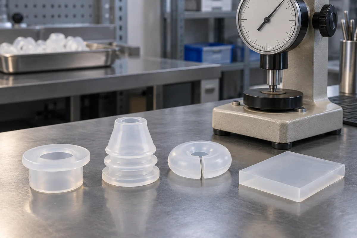
Product design illustrations. Final geometry, materials and acceptance criteria are project-specific.
A softer silicone grommet may be easier to install, but that does not make it a better seal in every assembly. Hardness is one material characteristic within a system that also includes the lip shape, panel, cable and service exposure. Choosing a compound by Shore A alone can hide the reason a sample succeeds or fails.
Begin by describing what the grommet must do after installation. Is it primarily edge protection, a locating feature, a water barrier or a combination? If it must hold a cable against movement, define that requirement separately. The deformation that helps a lip conform to a surface is not automatically the same behavior needed to resist a sustained cable load.
Understand what a hardness result does and does not describe
A Shore A result comes from an indentation method under specified conditions. It is not a direct measurement of the installed sealing force, tear resistance or long-term retention. Compare material data only with the method and specimen conditions in view. A reading from a thin curved flange may not be comparable with a value obtained from a suitable flat material specimen.
Ask how hardness will be checked for the project. If a witness coupon is used, document how its material and cure history represent the molded parts. Do not treat the coupon as proof of all properties of the final geometry. It supplies one controlled measurement that must be considered alongside dimensional and functional evidence.
Review shape before changing the compound
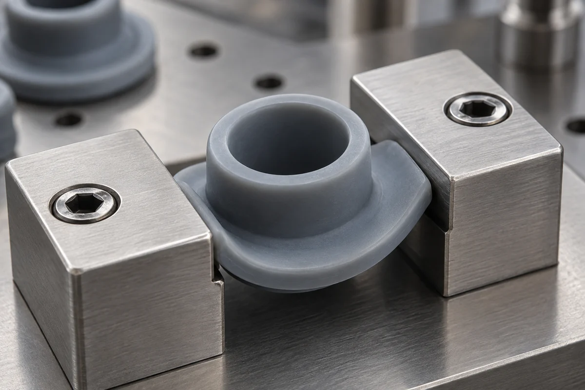
A thin flexible lip and a thick solid section can behave very differently in the same compound. The cable bore, groove width, local radii and available space for displacement determine where the elastomer moves. If the assembly is difficult to seat, first locate the obstruction. Changing hardness may conceal an unsuitable groove or sharp panel edge without resolving it.
Similarly, increasing interference can create more local deformation while preventing full seating elsewhere. Inspect the installed section or use a representative fixture to understand the contact path. The panel and groove dimensions should identify the relevant surfaces. An unexplained percentage of compression is not a substitute for a controlled interface.
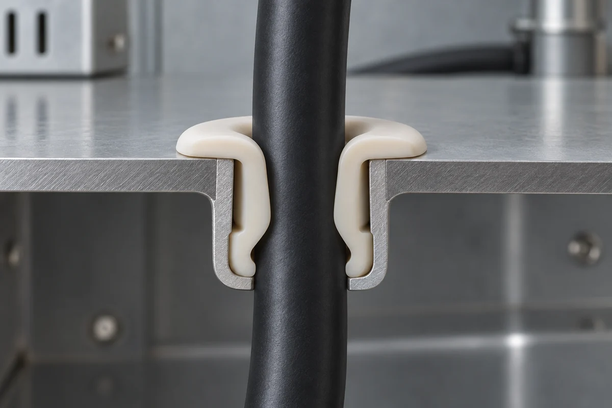
Consider the cable jacket as part of the deformable system. A stiff jacket, a soft jacket and an oval cable can produce different contact distributions even at the same nominal diameter. Evaluate the accepted cable variation rather than selecting one convenient sample. Changing the grommet material while leaving the cable uncontrolled makes the comparison difficult to interpret.
Balance installation with retained function
Document the installation sequence, access and any permitted assembly aid. A compound that makes installation easier may still need a redesigned lip to resist rolling or tearing. Conversely, a firmer option may require a geometry change to avoid excessive insertion effort. Compare complete candidate configurations instead of ranking compounds from softest to hardest.
Record observable failures such as a folded lip, incomplete seating, flange damage or displacement under cable movement. These observations connect the test result with a physical mechanism. A pass or fail alone cannot tell you whether to revise the material, change the groove, remove a sharp edge or control the installation procedure.
Separate initial softness from behavior over time
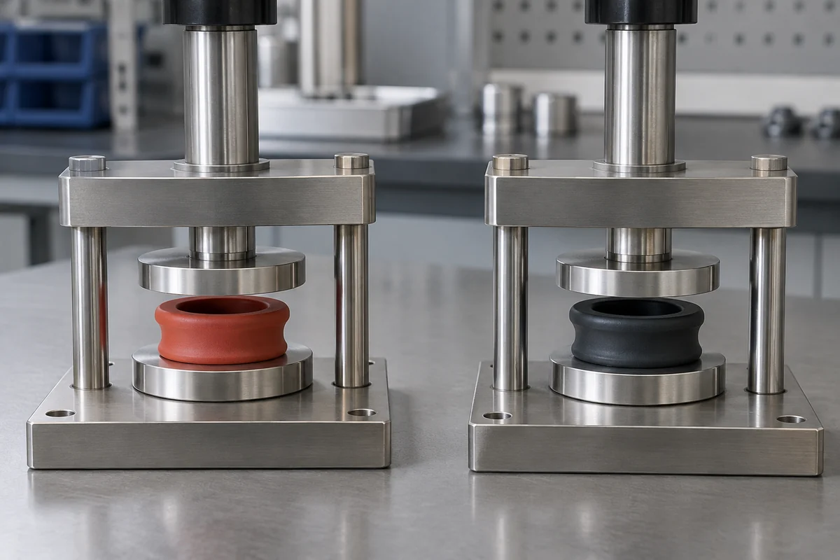
A freshly installed sample does not establish retained performance after time at temperature. Compression set and force relaxation are related to different observations: permanent deformation after a defined recovery differs from the force remaining while an assembly stays constrained. The Parker O-Ring Handbook discusses elastomer sealing behavior; its O-ring design values should not be copied directly into a different grommet geometry.
Define an aging evaluation using the application conditions and agreed measurement points. Record the starting configuration, exposure duration, temperature and recovery procedure. Then examine the part and repeat the functional checks that matter to the application. A material data-sheet result may help compare candidates, but it does not remove the need to review the assembled contact design.
Cleaning exposure may need a separate sequence or a combined sequence with aging. If the grommet is wiped while installed and stretched around a cable, test that state when relevant. An unstrained flat coupon answers a narrower question. Our cleaning-validation guide explains how to keep the exposure and acceptance records specific.
Choose a documented combination, not a universal number
Use a controlled comparison with identified compounds, drawing revisions and mating parts. If multiple factors change together, treat the outcome as evidence for the combined configuration, not proof that hardness alone caused the improvement. Keep rejected options and the reason for rejection in the development record so the same decision is not repeated later.
The final material specification should name the accepted grade and relevant controls, while the assembly specification identifies the geometry and tests that justified its selection. Neither a soft feel nor a nominal Shore A range is a universal sealing guarantee. The useful result is a repeatable part-and-assembly definition that can be checked when materials or suppliers change.
Review a defined cable-entry assembly
Explore our custom LSR silicone cable grommets and the cable-grommet pilot validation case study. Send the part drawing, panel and cable specifications, service conditions and acceptance plan to scope tooling, molding and inspection together.