
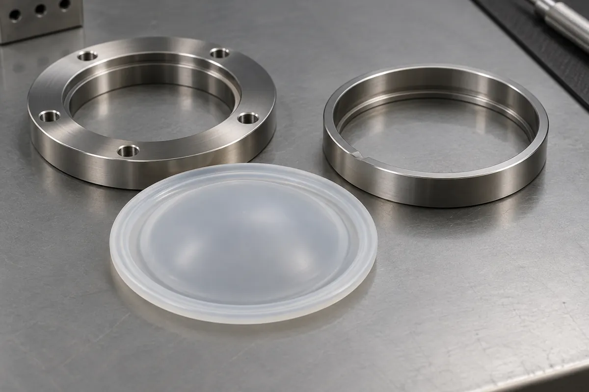
Product design illustrations. Final geometry, materials and acceptance criteria are project-specific.
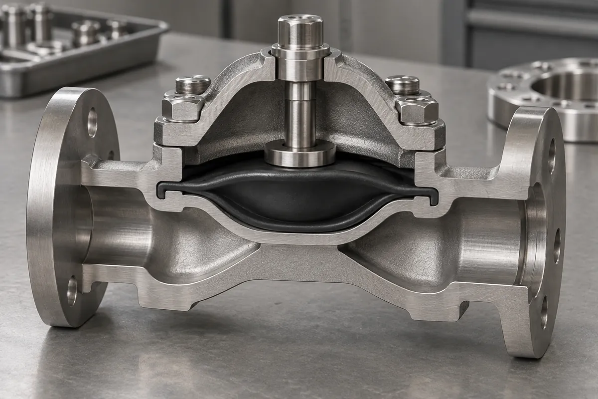
A diaphragm can have a suitable membrane and still leak because its clamped edge is poorly controlled. The bead, groove, flange and fasteners form the static sealing interface. Their job is to retain and seal the diaphragm without cutting it, allowing it to slip or disturbing its intended movement.
Review the two functions separately at first. Identify how the edge is held and how the active membrane moves. Then examine their connection, because changing the clamp depth or the transition radius can alter the flexible span and the force response of the assembled component.
Locate the diaphragm without damaging it
A bead or locating feature can help establish a repeatable position, but it needs room to seat correctly. Check the installation path, groove entry and any sharp edges. A feature that looks positively retained in a section view may be difficult to assemble without twisting or pinching the elastomer.
Define how the installer can recognize correct seating. Hidden folds beneath a cover can produce inconsistent results that appear to be material variation. A practical locating scheme should reduce this uncertainty without requiring excessive force or an improvised tool that can mark the flexible part.
The bead-and-groove discussion in the DiaCom design guide provides relevant background. Final dimensions still need to match the actual compound, construction and hardware rather than being copied from an unrelated example.
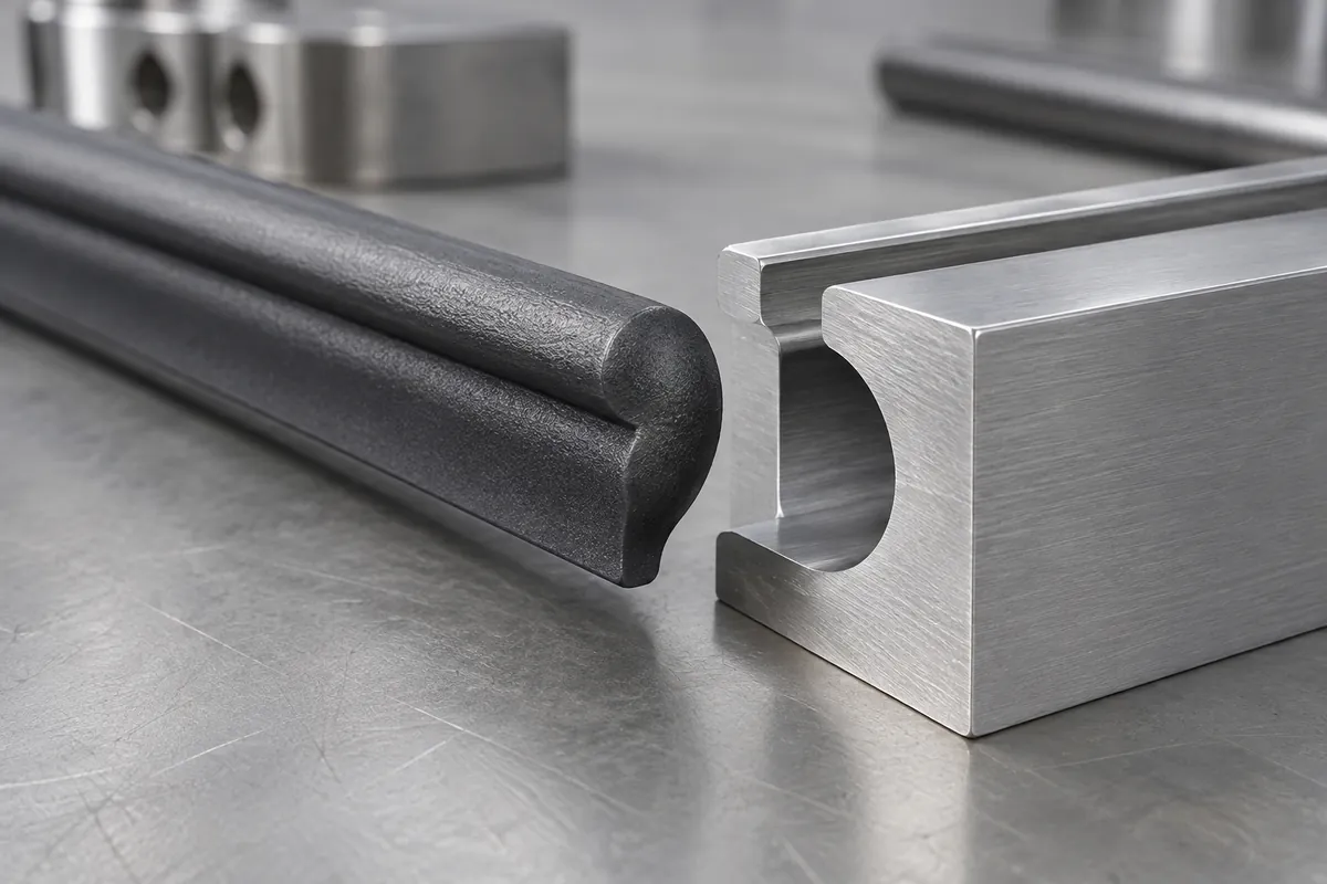
Control compression through the hardware
Consider whether the assembly uses a defined mechanical stop or relies primarily on fastening torque. Torque alone can produce different clamp conditions as friction, fastener condition or housing stiffness changes. The design review should explain how the required compression is established and how excessive compression is prevented.
Include housing flatness and fastener spacing. A flange that closes near the bolts but remains open between them can create an uneven sealing condition. Testing one carefully tightened sample does not establish that all allowed hardware tolerances will produce the same contact around the perimeter.
Separate the sealing contact from clearance for the moving membrane. The edge of the housing should not become an unintended cutting or rubbing surface at maximum travel. Review both pressure directions and the permitted overtravel, not only the resting position shown in a nominal assembly.
Measure interfaces in meaningful conditions
Specify which diaphragm dimensions are checked in the free state and which are confirmed by assembly. Flexible beads can deform during inspection, so agree the contact method and support. A tightly toleranced drawing without a repeatable measurement procedure creates disagreement rather than better control.
Inspect the housing references that establish the sealing gap and membrane position. It is not enough to measure the elastomer while assuming the mating hardware is nominal. If several housing suppliers are used, verify their accepted variation against the same functional interface.
Record the tightening sequence and any assembly aids used during validation. Lubricants or cleaning residues can change installation and may affect compatibility. Do not introduce an aid during production simply because it makes assembly easier without reviewing its effect on the approved seal and application.
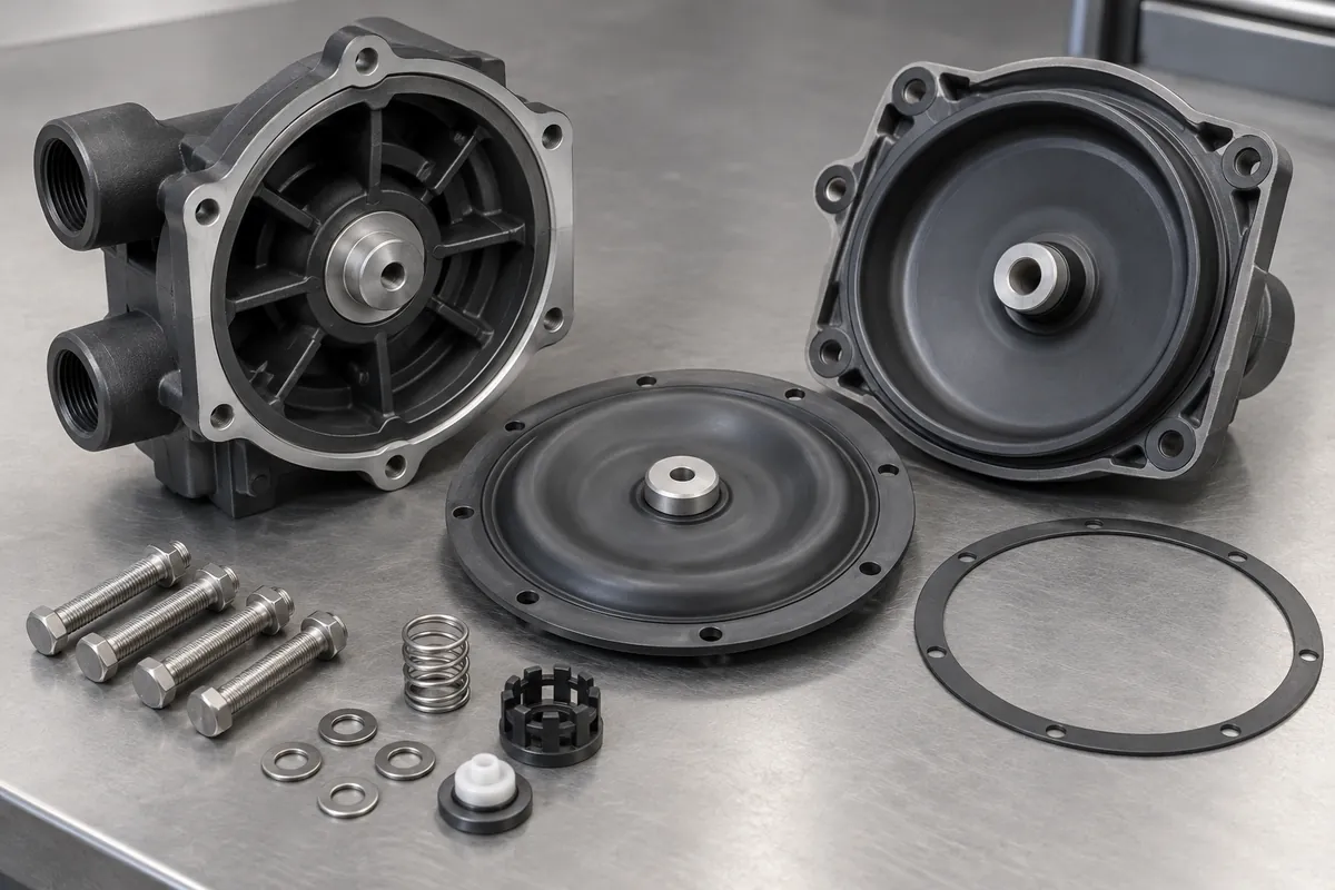
Use failures to identify the responsible boundary
When leakage occurs, distinguish a flange leak from a membrane defect or a leak elsewhere in the fixture. Record the pressure, duration, medium and detection method. Replacing a diaphragm until one sample passes can hide an unstable assembly process rather than establish a reliable component specification.
Coordinate the clamp review with diaphragm shape selection and the planned cycle test. A static seal at one position is only one part of the operating requirement when the center moves repeatedly under pressure.
Keep the approved hardware, fasteners, diaphragm revision and assembly method together in the release record. A later change to the groove depth or cover stiffness is a functional change even if the diaphragm drawing remains untouched. That traceability makes recurring leakage investigations much more focused.
Discuss the component and its acceptance requirements
Explore our custom silicone diaphragms and the related project case study. Send the current drawing, mating-part details, operating conditions and required quantities. We can review tooling, molding and inspection as a defined supply scope, with development samples and production approval kept separate.